Operation – Lincoln Electric IM827 POWER FEED 10M WIRE FEEDER User Manual
Page 27
b-4
OPERATION
b-4
ITEM
DESCRIPTION
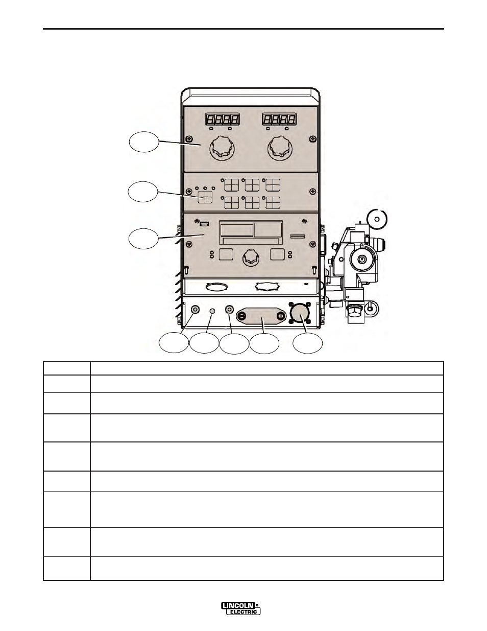
1
Status LED indicates system status.
2
Digital Meter Display is a bright LED display of key welding information. Adjusting Parameter Knobs.
3
MSP4 Panel is used to set the weld mode, adjust the arc, change arc start/end parameters and for set-
up information.
4
Cold Feed - Gas Purge Switch, press the switch up to feed wire with weld output off. Press the switch
down for gas flow with weld output off.
5
2 step - 4 step Switch is used to choose between a 2 step trigger or a 4 step trigger operation.
6
Memory Panel. Operating Instructions are located in this Operation Section if your machine is equipped
with this unit. If not equipped you may order K2360-1 Field-Installed option (See Accessories Section).
(Memory Panel are for Codes 11771, 11772 and above)
7
Cover for Optional Water Cooling Kit, remove when the water cooling kit is installed. See instructions
with water cooling Kit.
8
Trigger Connector 5-pin amphenol for connecting the MIG gun trigger. See Installation Section for detail.
POWER FEED
®
10M SINGLE WIRE FEEDER
2
6
3
5
1
4
7
8
FRONT PANEL CONTROLS AND CONNECTIONS
CASE FRONT CONTROLS
FIGURE b.1