Accessories – Lincoln Electric IM542 INVERTEC POWER WAVE 450 ROBOTIC User Manual
Page 49
ACCESSORIES
D-9
D-9
POWER WAVE 450
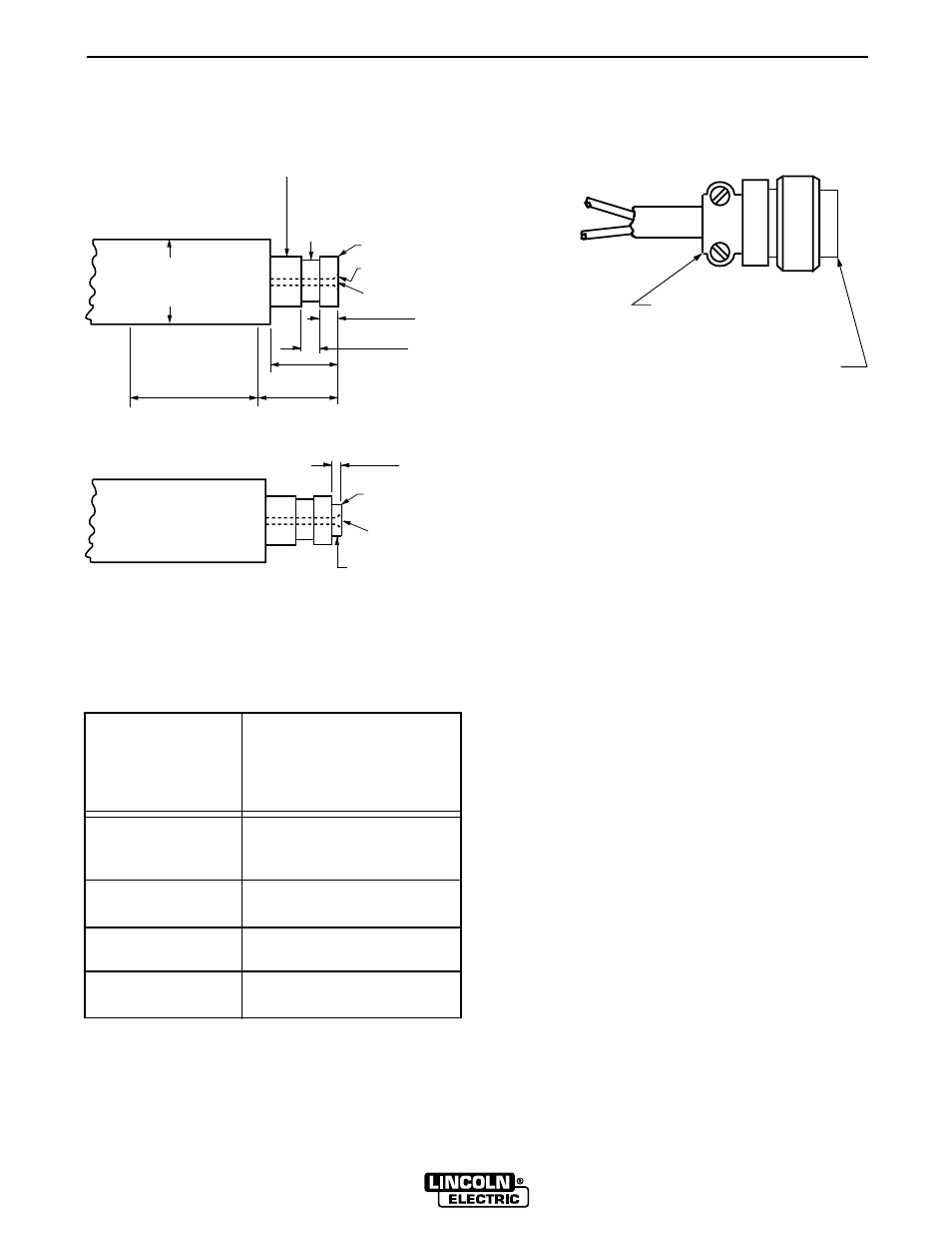
Gun Cable Connector Requirements
to Permit Proper Connection to Wire
Feed Units
Connector must be
insulated in this area
Style "A"
1.25 max
(31.7)
2.00
(51.0)
1.25
(31.7)
1.00
(25.4)
.252 (6.40)
.260 (6.60)
.295 (7.49)
.290 (7.36)
"A" DIA HOLE
.062R (1.5R)
.03 x 45
° (.76 x 45°)
.749 (19.0)
.747 (18.9)
.62 (15.7) DIA.
Connector for 1/16 - 5/64” (1.6 - 2.0 mm) Wire
Connector for .023 - .052” (19.0 / 18.9 mm) Wire
(For all other dimensions, See Diagram above).
NOTE: Connector part with .749/.747 (19.0/18,9 mm)
diameter should be made from brass if it is to be part
of the welding current carrying circuit.
Style "B"
.03 x 45
° (.76 x 45°)
"A" DIA HOLE
.180 (4.5)
.160 (4.0)
.495 (12.5) DIA. MAX.
“A” Diameter Hole
to be Concentric to
Wire Size
.749/.747 (19.0/18.9 mm)
in. (mm)
Diameter Within .008 (.20) F.I.M.
.068- 5/64
.125 [1/8 (3.2 mm) Drill]
(1.7-2.0)
1/16 (1.6)
.078 [5/64 (2.0 mm) Drill]
.045 & .052 (1.1 & 1.3)
.062 [1/16 (1.6 mm) Drill]
.023-.035 (0.6-0.9)
.055 [(1.4 mm) #54 Drill]
All dimensions in inches and (millimeters)
Switch Requirements
1/2 Amp AC 24 Volts - Inductive
1/2 Amp DC 24 Volts - Inductive
To Gun Switch
Connect Leads to
Pins "A" & "C"
S12024-1 (L.E. Part No.)
Amphenol AN3057-10 (or equiv.)
S12020-6 (L.E. Part No.)
Amphenol MS-3106A-18-11P (or equiv.)