Installation, Output connections – Lincoln Electric IM542 INVERTEC POWER WAVE 450 ROBOTIC User Manual
Page 14
INSTALLATION
A-4
A-4
POWER WAVE 450
2
3
1
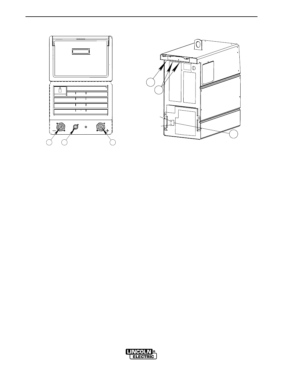
FIGURE A.3 – FRONTPANEL/BACK PANEL
1 WORK TERMINAL
2 ELECTRODE TERMINAL
3 REMOTE CONTROL AMPHENOL RECEPTACLE
4 WATER COOLING FITTINGS (ON ACCESS PANEL)
5 WIRE FEEDER CONNECTIONS (ON BACK PANEL)
6 ELECTRODE TERMINAL
To reconnect your machine for the proper input volt-
age, see the reconnect instructions on your input
access door and:
1. Move the large input voltage switch to the
proper position according to your input volt-
age, and the labels near the switch.
2. Move the auxiliary “A” lead to the appropriate
terminal, according to your input voltage and
the labels near the terminals.
OUTPUT CONNECTIONS
See Figure A.3 for the location of the work terminal,
electrode terminal, remote control amphenol recepta-
cle, water cooler fittings and wire feeder connections.
WORK AND ELECTRODE CABLE
CONNECTIONS
Size
Use the largest welding (electrode and ground) cables
possible — at least 70mm
2
(#2/0) copper wire — even
if the output current does not require it. When pulsing,
the pulse current often exceeds 650 amps with the
Power Wave 450. Voltage drops can become exces-
sive if undersized welding cables are used.
Routing
To avoid interference problems with other equipment
and to achieve the best possible operation, route all
cables directly. Avoid excessive lengths, bundle the
electrode and ground cables together where practical,
and do not coil excess cable.
WATER COOLER CONNECTIONS
The water cooler fittings are a quick-connect type.
Refer to the Accessories and Maintenance sections of
this manual for water cooler operation and recom-
mended coolants.
WIRE FEEDER CONNECTIONS
Refer to the Accessories section for Wire Feeder Con-
nections.
Refer to Setup overlay in Operation section for Wire
Feeder Configuration.
4
(OUT)
(IN)
6
5