Hired hand, inc – Hired-Hand Evolution Series 3000/3001: Humidity Transmitter User Manual
Page 2
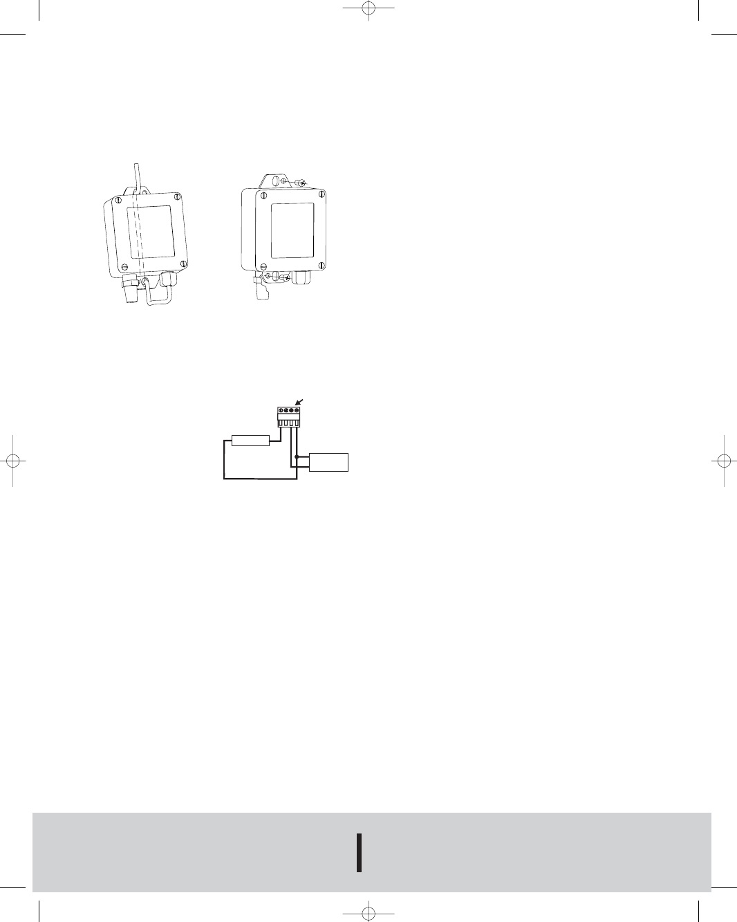
MOUNTING
The transmitter should be mounted with the sensor pointing
downward to prevent water collection in the housing. The integral
mounting tab has two sets of mounting holes. The larger holes are
for the suspension mounting and the smaller holes are for surface
mounting the transmitter to a wall. Please see figure 1 and 2 for
more information on both mounting methods.
WIRING
Use maximum 18 AWG wire for wiring terminals. Refer to figure 3
and 4 for wiring information.
0-10V Output Models
The 0-10V output models may
be powered with 13-35 VDC.
Note polarity. The maximum
load is 2 mA (5 k ohms). Wire
as shown in Figure 3.
Figure 3
HIRED HAND, INC.
Phone: 256/287-1000
P.O. BOX 99 • BREMEN, ALABAMA 35033, U.S.A.
Fax: 256/287-2000
www.hired-hand.com
©Copyright 2007 Hired Hand
Printed in U.S.A. 10/07
FR# 03-195967-10 Rev.2
+
-
RH RECEIVER
TEMP. RECEIVER
TEMP. RECEIVER
OBSERVE CORRECT POLARITY FOR DC POWER
+
-
+
-
POWER
SUPPLY
TERMINAL
BLOCK
SCREWS
FINAL INSPECTION
0-10 V Output Models:
Verify appropriate supply voltage. The 0-10V output models
require a DC supply of 13 to 35 V for proper operation maximum.
Maximum load is 2 mA.
MAINTENANCE
Upon final installation of the Series EV Humidity Transmitter and
the companion receiver, no routine maintenance is required. A
periodic check of the system calibration is recommended. The
Series EV is not field serviceable and should be returned if repair
is needed (field repair should not be attempted and may void
warranty). Be sure to include a brief description of the problem
plus any relevant application notes. Contact customer service to
receive a return goods authorization number before shipping.
Figure 1
Suspension Mounting
Figure 2
Surface Mounting
H-WHT-S 10/17/07 8:44 AM Page 2