Hired-Hand Super-Savers (Forced Air Heaters) XL: Direct Wire Flame Probe Kit User Manual
Page 2
HIRED-HAND MFG., INC.
• 1733 County Road 68 • Bremen, Alabama 35033 USA• Phone 256-287-1000 • Fax 256-287-2000
Manual Part No. 4802-5082 rev 3-06 Page
2 of 2
NOTE
If necessary for easier access, the door can be
removed by loosening the flat-headed screw at the
bottom of the door. Slide the bottom of the door
outward and down for removal.
10. Use a flat screwdriver to push-out the grommet inside
the nylon fitting. Discard this grommet.
11. Place the supplied tube through the nylon fitting
allowing the tube to show equally on both ends.
Refer to Figure 7.
FIGURE 7
FIGURE 8
12. Connect the replacement wire connector to the
electronic module connection block in the same
position as previously removed. Refer to Figure 5.
13. Place the replacement wire through the nylon nut, flat
washer, knock-out hole, flat washer, tube and nylon
fitting in specific order and tighten the nylon nut.
Refer to Figures 8 & 9.
FIGURE 9
FIGURE 10
14. Use the 15 mm open-end wrench to tighten the nylon
fitting securely while holding the internal nylon nut.
Do not over tighten. Refer to Figure 10.
NOTE
The flat washers MUST be positioned to
COMPLETELY COVER THE KNOCK-OUT HOLE.
15. Tighten the Nylon Domed Nut until the wire is
securely held in place.
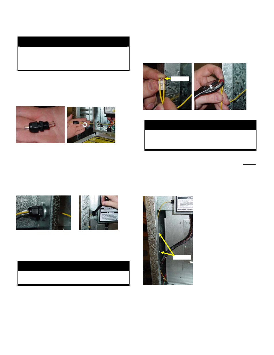
16. Use the supplied IDC (Insulation Displacement
Connector) and connect the Yellow wire from the wire
sleeve and the new Yellow wire assembly. Refer to
Figure 11.
FIGURE 11
FIGURE 12
NOTE
Both wires must be inserted into the IDC completely
to the opposite side and remain in place until the
wires are securely crimped. Refer to Figure 11.
17. While holding the wires securely in place, use the
wire pliers to press the connector’s red button almost
flush with the connector’s clear body. Do not crush
the connector past this point. Refer to Figure 12.
18. Visually examine the clear back side of the connector
for correct wire placement and the red button for
proper crimp.
19. Slightly form the Yellow
wires so that the connector is
pointing upward and the wires
are behind the door flange.
DO NOT PLACE THE WIRES
WHERE THE DOOR CAN
CONTACT THE WIRES
WHEN CLOSED. Refer to
Figure 12.
20. Use the two supplied
cable ties and the two door
flange holes to secure the
Yellow wires behind the door
flange. Refer to Figure 13.
21. Cinch the cable ties, cut
off the excess strap, and
rotate the cable tie heads
behind the door flange.
FIGURE 13
Wire Ends
Cable Ties