Diagram 1 exploded view of brooder – Hired-Hand Super Glo Brooders (Infrared): Zone Infrared User Manual
Page 2
Part No. 4801-5107 Rev 7-06
Zone Infrared Brooder
Page
2
of
4
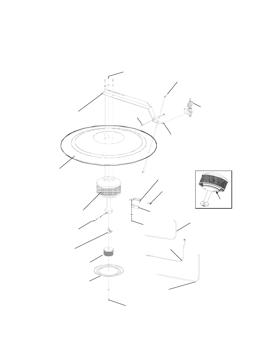
Diagram 1
Exploded View of Brooder
1/4-20 x 3/4 Screw
#8-32 x 1/2 Screw
Gas valve
support bracket
Gas valve
Assembly
6410-6306
Low Profile
Hanging Bracket
0404-4733
Canopy
6410-6300
Burner assembly
LP 6410-6302
NG 6410-6303
Igniter
Bracket
Pilot
Orifice
Burner orifice
6410-6308 NG
6410-6307 LP
37"(94 cm) T-couple
sensor 3003-5011
Catch plate
0404-4451
Dust screen
6410-6317
Gas tube for pilot
0403-4471
Pilot
Guide
Gas tubing for
burner 0403-4472
Igniter shield
#10 x 1/2
Screw
#10 x 1/4
Screw
1/4-20 x 1/2
Screw
1/4-20 x 1/2
Screw