3 operating instructions – Condec PIN7010 User Manual
Page 8
4
PIN7000/PIN7010 Operation and Maintenance Manual
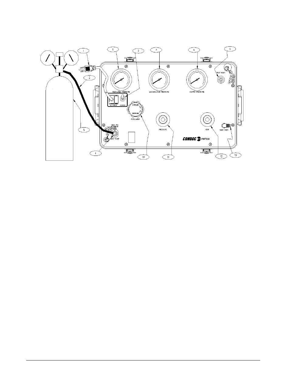
Figure 2-1. Initial Setup/Operating
NOTE: PIN7000 shown, AC Input (1), Test Port (9) and Input Port (4) are on back side of PIN7010 Rack Mountable
Intensifier.
2.3
Operating Instructions
NOTE: See Figure 2-1, when following these steps.
1. Optional External Cylinder: Open the cylinder valve (5) by rotating counter-clockwise slowly until it
stops.
Other: Open the, customer supplied, pressure source valve.
2. Using the REGULATOR (10), adjust the maximum intensifier pump input pressure, as read by the
REGULATED PRESSURE gauge (6), to 1/10 of the target value. The unit utilizes an internal intensifier
with a 10:1 ratio. As an example, setting regulated pressure to 300 PSI would generate an output pressure
of 3,000 PSI. Using this technique, the device to be pressurized, is fully protected from being
accidentally over-pressurized.
3. To generate pressure, enable the
POWER
switch (2) and monitor the pressure as it builds in the
ACCUMULATOR PRESSURE gauge (7). Turn the
POWER
switch (2) off when 10% more than the
target pressure has been achieved.
NOTE: The intensifier POWER switch (2) can be operated in two modes. The up position is continuous and the down
position is momentary/jog.
4. To apply pressure, the
VENT
valve (12) must be closed. Open the
PRESSURE
valve (11), slowly
counter-clockwise, while monitoring the
OUTPUT PRESSURE
gauge (8), until reaching the target value.
5. Use either the
PRESSURE
(11) or
VENT
valve (8) to obtain a specific pressure reading. Both provide
precise control. As the pressure approaches the desired value, the valve being used for control should be
rotated slowly clockwise to its closed position.
NOTE: Use the intensifier POWER switch (2) if the ACCUMULATOR PRESSURE gauge (7) reading falls below required
target pressure value.