1 panel/chassis removal and installation – Condec PIN7010 User Manual
Page 10
6
PIN7000/PIN7010 Operation and Maintenance Manual
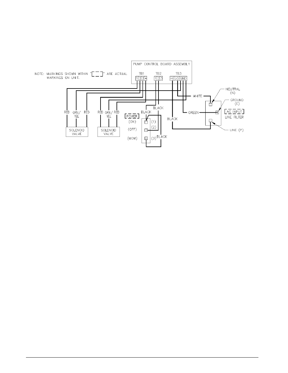
Figure 3-1. PIN7000/PIN7010 Wiring Diagram
3.2.1
Panel/Chassis Removal and Installation
PIN7000 Removal
Tools required: Phillips screwdriver
1. Loosen and remove the 10 screws (PN 14862) that secure the panel assembly to the enclosure.
2. Lift the panel and chassis by first grasping the regulator knob and test port and second, grasping under
the panel edges. Tilt the panel at an angle by lifting the right side before the left side as you face the
panel. Ensure that the wire harnesses do not catch and snag.
3. Gently set the panel/chassis assembly on a bench top. It can be rested on the panel bottom with the
accumulator supported by a screwdriver handle.
PIN7000 Installation
Tools required: Phillips screwdriver
1. Lift the panel and chassis by first grasping the regulator knob and test port.
2. Gently place panel/chassis assembly into enclosure. Tilt the panel at an angle by lifting the right side
before the left side as you face the panel. Ensure that the wire harnesses do not catch and snag.
3. Align mounting holes and install the 10 screws (PN 14862) that secure the panel assembly to the
enclosure.
PIN7010 Removal
Tools required: Phillips screwdriver
1. Loosen and remove the 14 screws (PN 14861) from top, bottom, and sides that secure the panel assembly
to the enclosure. Also, loosen and remove the three screws (P/N 14861) from the rear of unit that secure
the enclosure to the TEST PORT/AC INPUT/INPUT PORT panel.
2. Lift the panel and chassis by grasping the handles located on the front of the rack mountable panel.
Ensure that the wire harnesses do not catch and snag.
3. Gently set the panel/chassis assembly on a bench top. It can be rested on the panel bottom with the
accumulator supported by a screwdriver handle.
PIN7010 Installation
Tools required: Phillips screwdriver
1. Lift the panel and chassis by grasping the handles located on the front of the rack mountable panel.