Condec DLR334 Series User Manual
Page 4
2
.
♦
Trip point settability:
Set in display (engineering) units with resolution of
the base unit configuration. In “run” mode set in
base.
♦
Trip point Hysteresis:
Set in display (engineering) units with resolution of
the base unit configuration to a maximum setting of
full scale.
♦
Output Relay:
Arrangement: Form C contact closure.
MaxSwitchingVoltage: 100VDC,220VAC
Max Current:
AC (resistive load) 120vac: 1 A
AC (resistive load) 220vac: 1/2 A
DC (resistive load): 1/2 A
♦
Output Logic:
Trip 1 on OUT 1 and Trip 2 on OUT 2. A logic
"O" is output "on" (energized).
♦
Output Activation select:
If set for "Under" the output relay is "ON"
(energized) when the data is below (under) the Trip
point or in the Trip Band, if band type selected. If
set for "Over" the output relay is "ON" when the
data is at or above (over) the Trip point or out of
the Trip Band.
♦
Power-up reset Protection:
All relays are held "off' until the CPU re-establishes
proper operating conditions caused by power
interruptions.
♦
Indicators:
Can be set in configuration for two types of display
indications. If set for "TRIP PTS", the display will
indicate the active outputs by "TRIP 1 ", "TRIP 2",
or TRIP 1 & 2". If set for "ACCEPT" the alpha
display will indicate "LOW', "ACCEPT" and
"HIGH" for trip band 1.
♦
Serial 1/0:
All Trip point parameters can be recalled or entered
via the Serial Full Duplex.
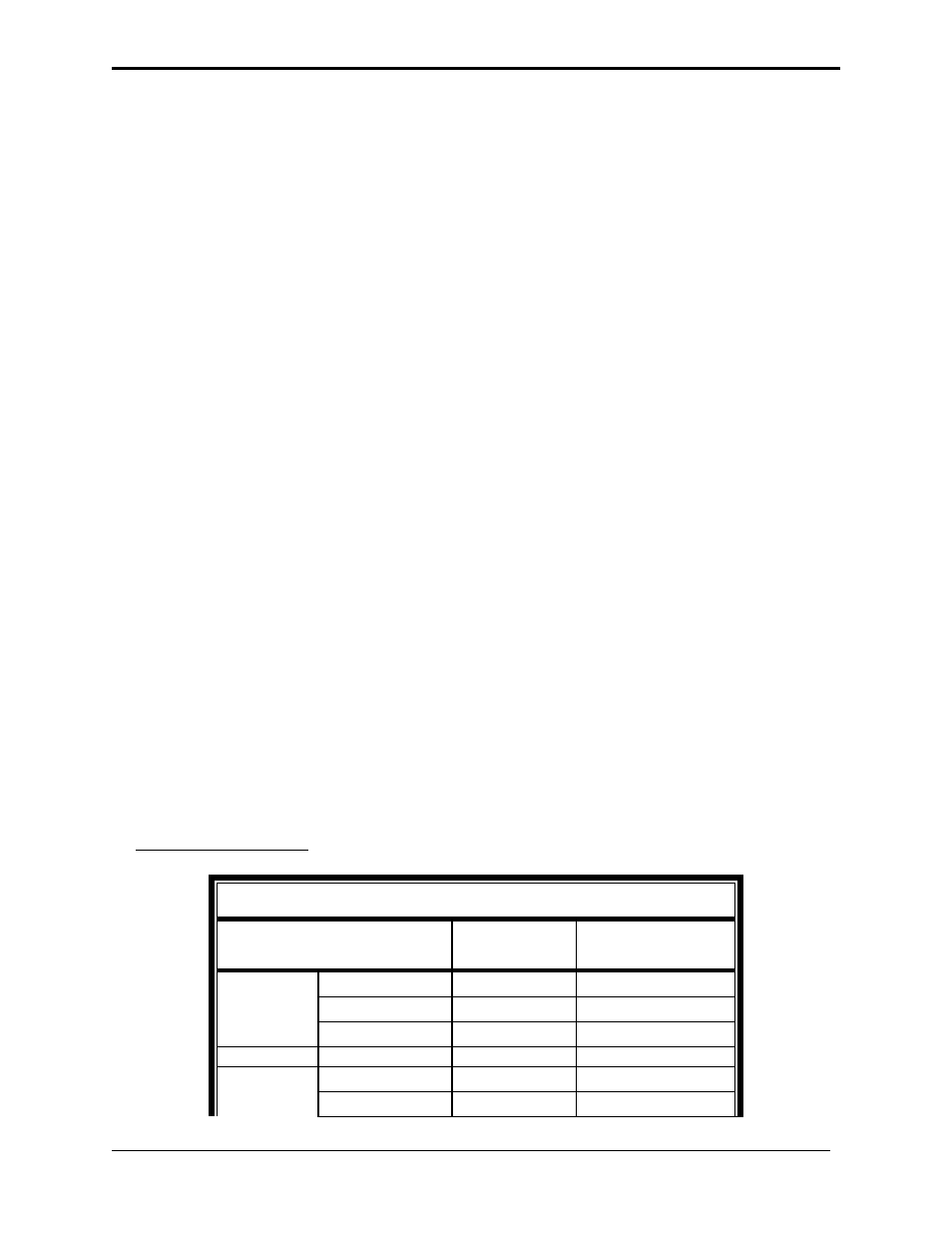
4. RELAY WIRING:
RELAY CONNECTIONS on OPTION BOARD
FUNCTION
BOARD
MARKING
RELAY BLOCK
POSITION
RELAY 1
OUT 1 N.C.
OUT 1 N.C
TB3-1
OUT 1 N.O.
OUT 1 N.O.
TB3-2
OUT 1 COM
OUT 1 COM
TB3-3
RELAY 2
OUT 2 N.C.
OUT 2 N.C.
TB3-4
OUT 2 N.O.
OUT 2 N.O.
TB3-5