Replacing a combined fru in a brocade vdx 6710-54, Figure 6, Example – Brocade VDX 6710-54 Hardware Reference Manual User Manual
Page 50: Figure 7
32
Brocade VDX 6710-54 Hardware Reference Manual
53-1002390-08
Replacing a combined FRU in a Brocade VDX 6710-54
5
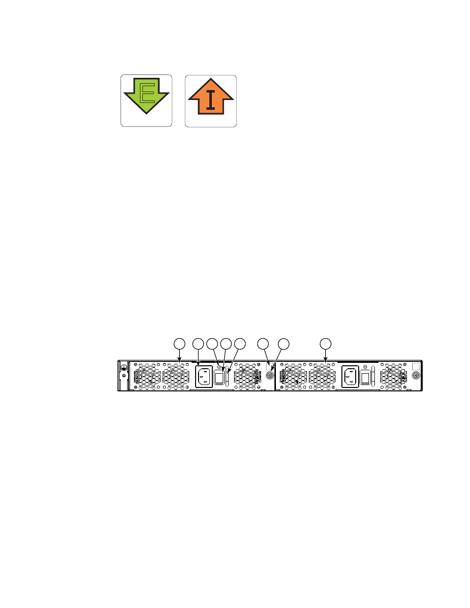
FIGURE 6
Examples of airflow symbols
The green E symbol indicates an exhaust FRU. This unit pulls air in from the port side of the switch
and exhausts it out the non-port side. This is called front-to-back airflow or forward airflow. This
symbol should appear on FRUs with part numbers ending with -F.
The orange I symbol indicates an intake FRU. This unit pulls air in from the non-port side of the
switch and exhausts it out the port side. This is called back-to-front airflow or reverse airflow. This
symbol should appear on FRUs with part numbers ending with -R.
The show environment fan command will indicate either “forward” or “reverse” airflow.
Replacing a combined FRU in a Brocade VDX 6710-54
shows the two combined AC power supply and fan assemblies in the Brocade VDX
6710-54. The Network OS identifies the FRUs from left to right as power supply and fan assembly
#2 and power supply and fan assembly #1.
shows the combined DC power supply and fan
assemblies.
FIGURE 7
Brocade VDX 6710-54 AC power supply and fan assemblies on the non-port side
AIRFLOW
E
AIRFLOW
1
Power supply and fan assembly #2
5
Handle
2
AC power cord receptacle
6
Airflow label
3
Status LED
7
Captive screw
4
On/off switch
8
Power supply and fan assembly #1
2
3
7
1
5
4
8
6