Step 3, Step 5, Step 4 – Anthro Fit Console Unit Assembly Instructions User Manual
Page 4: Step 6, Step 7, Step 8, Fcczz/xx3
3
/
4
” Wood Screw
325-5106-00
Support Screw
325-5010-00
Anthro
Corporation Technology Furniture
®
10450 SW Manhasset Drive Tualatin, Oregon 97062 1-800-325-3841
anthro.com
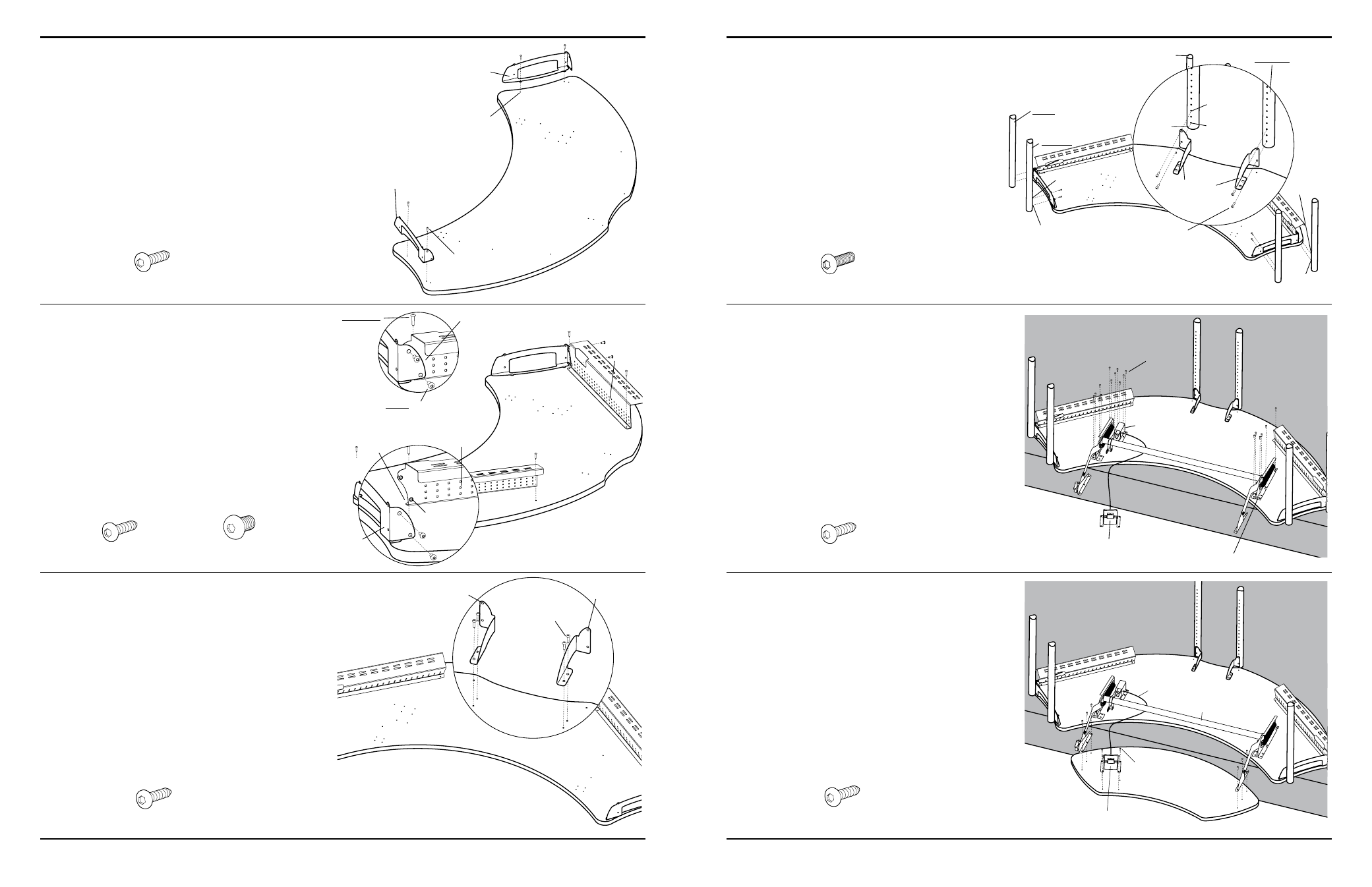
Step 3
Place your Console Large Shelf onto the floor with the
predrilled holes facing up.
Position both Small Support Brackets onto the Large
Shelf and align two of the holes on each Support with the
predrilled holes on the Shelf. Loosely secure each Small
Support to the Shelf using two Wood Screws per Support.
Step 5
Place each of the Connector Supports onto the top as
shown.
Align the two holes on each Support with the predrilled
holes on the Shelf, then secure each Support using two
Wood Screws.
Step 4
Place both Back Troughs onto the Console Large Shelf,
between the installed Support Brackets.
Align the two Threaded holes on each Back Trough with
those on the installed Support Brackets. Carefully, thread
one Button Head Screw through the Support Bracket, into
the Back Trough. Repeat for remaining three Button Head
Screws & Threaded Holes.
Insert two Wood Screws through the two remaining
Holes on each of the Back Trough flanges (which should
be aligned with two predrilled holes on the Shelf) and tighten
into place.
3
/
4
” Wood Screw
325-5106-00
3
/
4
” Wood Screw
325-5106-00
(
1
/
4
-20 X .50”) Button Head Screw
325-5003-00
Support Screw
325-5106-00
Step 6
Determine the best height for your Console Large
Shelf. These instructions will place your Shelf 31” from
the floor using the standard 3” Casters.
Attach both center Vertical Legs by loosely
installing
two Support Screws through each Connector Support
into Holes 1 & 3 from the top (non-coped end).
Loosely install two Support Screws through each Small
Support into holes 1 & 3 from the top of both front Legs.
Install two Support Screws through holes 1 & 3 from
the top of both rear Legs.
Step 7
(requires Shelf to be 12” from floor)
Place the Mechanism onto the Shelf Assembly.
Align the Mechanism Flanges with the predrilled Holes
on the Shelf underside.
Secure the Mechanism to the Shelf using a total of twelve
Wood Screws.
Align the six Holes of the Brake Assembly with those on
the Shelf.
NOTE: It may be necessary to depress the Paddle while
manipulating the Brake over the predrilled Shelf Holes.
Secure the Brake Assembly using a total of six Wood Screws.
Top
(non-coped)
end
Bottom (coped) end
Hole 1
Hole 3
(12” high surface shown shaded)
Paddle
Brake
Mechanism Flanges
FCCzz/xx3
Small Support
Bracket X
Small Support
Bracket Y
Small
Support
Bracket X
FIRST: install the But-
ton Head Screws
SECONd:
Install
the Wood
Screws
Back
Trough-Y
Back Trough
Flange
NOTe: Make sure the Back Supports
are in front of the Support Brackets.
Threaded
holes
Back
Trough-X
3
/
4
” Wood Screw
325-5106-00
Connector
Support-Y
Connector
Support-X
(12” high surface shown shaded)
Step 8
(requires Shelf to be 12” from floor)
Rotate the Console Caddy so the predrilled holes face up.
Slide the Caddy under the Mechanism and align the three
holes located on each end of the Caddy and Mechanism.
Secure the Caddy using a total of six Wood Screws. Then,
secure the Paddle to the Caddy using four Wood Screws.
NOTE: Make certain the Cable for the Paddle is positioned
underneath the Adjusta Bar.
Paddle
Adjusta Bar
Predrilled Holes
NOTe: For a final Large Shelf height that is lower than 31”,
adjust one hole down for each inch of variance desired.
Connector
Supports
Hole 1
Hole 3
Hole 1
Hole 3
FRONT Leg
REAR Leg
CENTER Leg
Cable
Wood Screw
Wood Screw
Support Screw
Wood Screw
Wood Screw