Anthro AnthroBench II 72 Assembly Instructions User Manual
72” anthrobench ii, Assembly instructions, Step 7
TECHNOLOGY FURNITURE
®
300-5599-00
300-5599-00
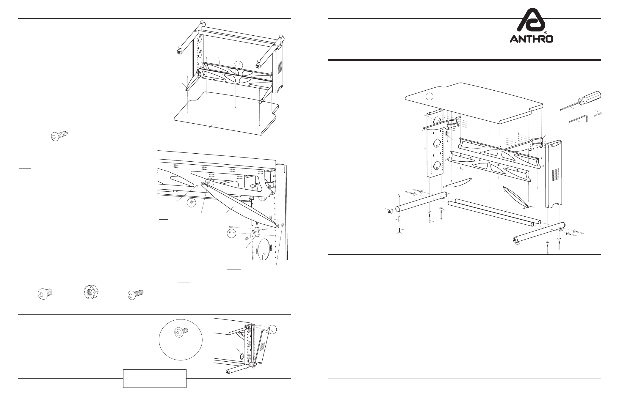
Enclosed Parts List
Detailed views of all Hardware is provided with each Assembly Step
Anthro
Corporation Technology Furniture
®
10450 SW Manhasset Drive Tualatin, Oregon 97062
SAVE THESE INSTRUCTIONS!
anthro.com
November 2013
04
06
07
03
02
09
05
08
01
10
13
11
14
12
15
16
17
18
19
72” AnthroBench II
Assembly Instructions
These Assembly Instructions are for the 72” AnthroBench models. Before beginning assembly of your AnthroBench, please
take a moment to review the parts listed below to verify that your shipment is complete.
Your AnthroBench is heavy!
Don’t try to lift it yourself. Work with
a buddy.
01– 30” Wide Bench Shelf
.............Qty. 1 ................(see below)
28” Deep
(ABS7229zz-xx and ABS7235zz-xx)
101-1126-00-00
36” Deep
(ABD7229zz-xx and ABD7235zz-xx)
101-1119-00-00
02– Bench Leg Assemblies
.............Qty. 2 .................(see below)
25” Bench Legs (ABS7229zz-xx and ABD7229zz-xx)
835-5008-00
31” Bench Legs (ABS7235zz-xx and ABD7235zz-xx)
835-5009-00
03– Bench Arm Left
........................Qty. 1 ............225-5357-00
04– Cross Ends
.................................Qty. 2 ...........225-5334-00
05– 1” Button-hd PB Screws
.........Qty. 12 ..........325-5580-00
06– Glide Insert Screws
..................Qty. 4 ............325-5052-00
07– 2.5” End Caps
............................Qty. 4 ...........175-5158-00
08– Glide Inserts
..............................Qty. 4 ............525-5030-00
09– Glides (
1
/
2
-13 X 2”)
...................Qty. 4 ............325-5165-00
*
10– Cap Screws (
5
/
16
-18 X 4”)
........Qty. 8 ............ 325-5166-00
11– Curved Washers
........................Qty. 8
225-2050-00 or 225-3522-00
12– Bench Base Tubes
.....................Qty. 2 .................(see below)
28” Deep
(ABS7229zz-xx and ABS7235zz-xx)
......125-5225-00
36” Deep
(ABD7229zz-xx and ABD7235zz-xx)
.....125-5183-00
13– 20” Bench Buttress
..................Qty. 2 ............225-5388-00
14– 65.5” Bench Cross Tubes
........Qty. 2 ............125-5186-00
15– Keps Nuts (
1
/
4
-20)
....................Qty. 8 ............325-5130-00
16– Pan Screws (
1
/
4
-20 X .5”)
........Qty. 8 ............325-5003-00
17– Bench Arm Right
......................Qty. 1 ............225-5358-00
18– Support Screws
........................Qty. 20 .......... 325-5010-00
19– 72” Bench Pans
.........................Qty. 2 ............225-5372-00
All Screw quantities listed here are the minimum needed
for your Bench assembly. There may be a few extra Screws
included, which are not counted in the Parts List.
To make the assembly of your Anthro Bench even easier, we
have included the required tools. The handy Hex Driver Bit
can be used in your electric drill in place of the Hex Driver.
20 - Hex Driver
5
/
32
”
.........................Qty. 1 ............375-5000-00
21 - Hex Driver Bit
5
/
32
”
...................Qty. 1 ............375-5003-00
22 - Hex Key
1
/
4
”
...............................Qty. 1 ............375-5024-00
3-Way Wrench
(not shown) ..........Qty. 1 ............225-5196-03
Step 7
Place the Bench Shelf
(laminate facing down) onto the floor.
With the help of another person, carefully rotate the Base Assembly
(from Step 6) over onto the Shelf.
Position the holes on the Pans and Arms to align with the twelve
predrilled holes on the Shelf. Insert two 1” Button-hd PB Screws
through each center opening of the Bench Pans
(shown encircled at
right).
Install the remaining PB Screws into each of the Arms and Pans. A
total of twelve PB Screws will be installed.
If a drawer and/or keyboard caddy are a part of this configuration,
install them now using their instructions. If the 5” casters upgrade is
part of this configuration, remove the glides and install the casters now.
With the help of a buddy, carefully rotate your AnthroBench right side
up.
Step 8
(requires a 3-Way Wrench)
FIRST- from the rear of your Bench, align one Buttress with
one hole on the Back Pan. Install a Pan Screw through the
Buttress and loosely capture using a Keps Nut on the opposite
side.
SECOND- position one Cross End on the remaining Buttress
end and install a Pan Screw and Keps Nut in the same manner,
but do not fully tighten.
THIRD- rotate the Buttress to align the Cross End with two
openings on the Leg. Secure the Cross End to the Leg using
two Support Screws.
Repeat this entire procedure for the remaining Buttress and
Cross End on the opposite end.
Tighten all Pan Screws, Support Screws and Keps Nuts.
Congratulations! Your AnthroBench assembly is complete.
Please return the enclosed Registration Card to receive product
updates!
Thank you for choosing Anthro!
Questions?
1-800-325-3841
(
1
/
4
-20 X .5”) Pan Screw
325-5003-00
(
1
/
4
-20) Keps Nut
325-5130-03
Buttress
Back Pan hole
Support Screw
325-5010-00
FIRST Install this Pan Screw
SECOND Install this Pan Screw
THIRD Install the Cross End
Lower Metal Mounts
Cable Grommet
Workstation Screw
(not counted in Parts List)
325-5092-00
Removal of Leg Covers and Cable Grommets
Remove the Leg Cover by: 1. Using the Anthro driver, remove
the top two Workstation Screws. 2. Lift and tilt the Cover up
and free of the lower metal mounts.
Cable Grommets are snapped into and out of each of the
circular Leg openings.
NOTE: The purpose of the Buttress is not to sup-
port your Bench Shelf. It is intended to make
your Bench absolutely rigid under extreme weight
conditions.
Pans
Arms
Rounded Edge of Shelf
Predrilled holes
22
21
20
1” Button Hd PB Screw
325-5580-00