Anthro Large AnthroCarts 48W Assembly Instructions User Manual
48” wide anthrocart, Assembly instructions, Step 8
TECHNOLOGY FURNITURE
®
48” Wide AnthroCart
Assembly Instructions
01 – Insert Screws ............................
Qty. 4 ...................... 325-5052-00
02– 1.75” Large End Caps ............
Qty. 2 ....................... 175-5021-xx
03– Castor Inserts ..........................
Qty. 4 .................... 525-1000-00*
04– 2
3
/
8
” Locking Castors ................
Qty. 2 .................... 150-5003-03*
05– 2
3
/
8
” Non-Locking Castors .......
Qty. 2 .................... 150-5002-03*
06– Base Tube Screws ....................
Qty. 4 ...................... 325-5000-00
07– 48” Wide Base Tube ................
Qty. 1 ............................ (see below)
30” Deep Base Tube
(H12xx) ........................................ 125-5175-xx
36” Deep Base Tube
(H13xx) ........................................ 125-5176-xx
08– 23.875” Vertical Legs ..............
Qty. 4 ....................... 125-5020-xx
09– Wood Screws ...........................
Qty. 11 .................... 325-5106-00
10– Support Screws .......................
Qty. 14 .................... 325-5010-00
11– 46” Wide Bridge Pan ..............
Qty. 1 ....................... 225-5338-xx
Enclosed Parts List
Detailed views of all Hardware are provided with each Assembly Step.
12– Bracket Screws .........................
Qty. 4 ...................... 325-5149-00
13– 2.75” Pan End Bracket ...........
Qty. 2 ....................... 225-5343-xx
14– Clamp Screws ..........................
Qty. 4 ...................... 325-5086-00
15– Shelf Supports ..........................
Qty. 4 ....................... 175-5060-xx
16– Shelf Clamps .............................
Qty. 4 ....................... 175-5059-xx
17– 48” Wide Shelf ..........................
Qty. 1 ............................ (see below)
30” Deep Shelf
(H12xx) .................................................. 100-6333-xx
36” Deep Shelf
(H13xx) .................................................. 100-6334-xx
18– 1.5” Small End Caps ...............
Qty. 4 ....................... 175-5020-xx
19– 18” Bridge Side Gussets ........
Qty. 2 ....................... 225-5337-xx
All Screw quantities listed here are the minimum needed
for your Cart assembly. There may be a few extra Screws
included, which are not counted in the Parts List.
Anthro
®
Corporation Technology Furniture
®
10450 SW Manhasset Drive Tualatin, Oregon 97062
SAVE THESE INSTRUCTIONS!
Document # 300-5067-00
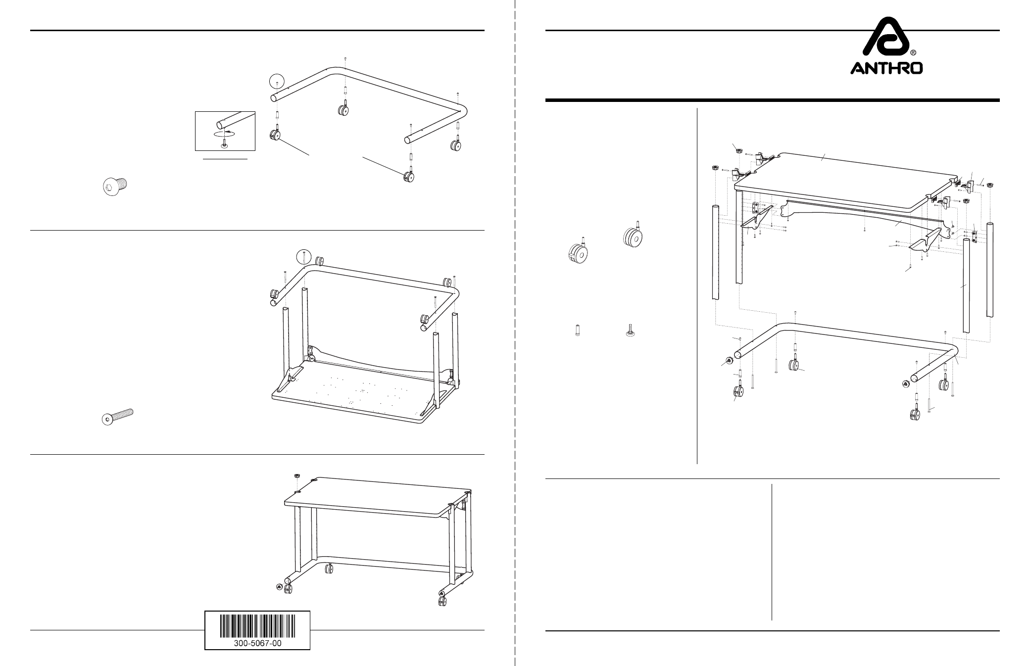
Step 8
Install all four Castor Inserts into the Base Tube and
secure with one Castor Screw per Insert.
Push the Castors, (locking ones in front) into the
Castor Inserts.
Step 9
Place the Base Tube Assembly (from Step 8) onto the
Vertical Legs of the Shelf Assembly (from Step 7).
Attach the Base Tube to the Legs using a total of four
Base Tube Screws.
TIGHTEN ALL SCREWS.
Step 10
Carefully, rotate your Cart over onto the Castors.
Pop the 1.5” Small End Caps into the Vertical Legs and the
1.75” Large End Caps into the Base Tube.
Congratulations! Your assembly is complete.
Please return the enclosed Registration Card to receive
our product updates, new catalogs, and sale flyers.
Thank you for choosing Anthro!
Printed in USA December 2000 Rev. A
These Assembly Instructions are
for the H12xx & H13xx.
Before beginning assembly of your 48” Wide
AnthroCart, please take a moment to re-
view the parts listed below to verify that
your shipment is complete.
"
Does your Cart have 4” Castors?*
(Such as an H12xx4. Your Castor Part
Numbers are given here.)
"
Does your Cart have Glides?*
(Such as an H12xxGL. Your Glide and Glide
Insert Part Numbers are given here.)
4” Locking Castor
150-5011-03
4” Non-Locking Castor
150-5010-03
Glide Insert
525-1004-00
Glide
325-5042-00
04
06
07
03
02
09
11
05
01
08
12
Base Tube Screw
325-5000-00
Castor Screw
(small pink patch on end)
325-5052-00
GLIDES ONLY
Thread each Glide
into the Glide Inserts
Locking Castors
To make the assembly of your 48” Wide
AnthroCart
even easier, we have included
all of the required tools. The handy Hex
Driver Bit can be used in your electric
drill in place of the Hex Driver.
Hex Driver
5
/
32
" ...........
375-5000-00
Hex Driver Bit
5
/
32
" ....
375-5003-00
8 oz. Rubber Mallet .....
375-5022-00
Questions?
1-800-325-3841
13
14
15
16
18
19
10
1.5” Small End Cap
1.75” Large End Cap
17