Step 9, Step 10, Step 2 – Anthro Fit Console Unit Assembly Instructions User Manual
Page 3: Step 1a, Step 1b, Step 11, Detail view, Hex key, Fcczz/xx3
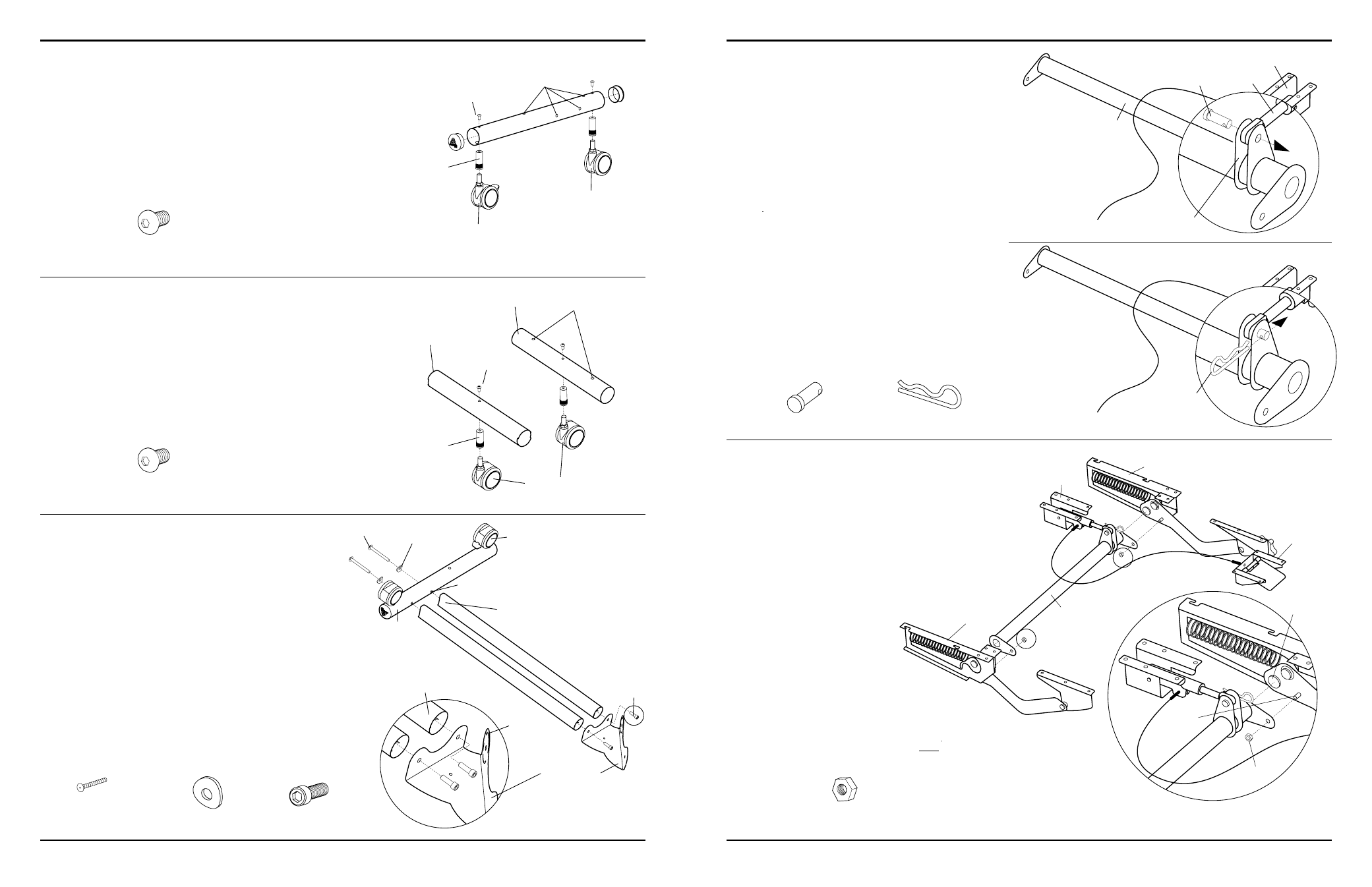
Step 9
Insert two End Caps into the ends of both 21” Base Tubes.
Install two Caster Inserts into each Base Tube and
secure with one Insert Screw per Insert.
Insert one Locking and one Non-Locking Caster into
each Insert of a Base Tube as shown.
Step 10
Install one Caster Insert into both the 15.27” & 15” Base
Tubes and secure each Insert with one Insert Screw.
Insert one Non-Locking Caster into each Insert of both
Base Tubes as shown.
Anthro
Corporation Technology Furniture
®
10450 SW Manhasset Drive Tualatin, Oregon 97062 1-800-325-3841
anthro.com
Step 2
(uses the 3-Way Wrench)
Unpack the remaining Adjusta Mechanism components
and arrange them as shown at right.
Place one Crossbar end onto the lower Crossbar
Button and Threaded Bolt (located on each of the Arm
Mechanisms). Secure the Crossbar to the Arm Mechanism
using one
5
/
16
” Hex Nut onto the Threaded Bolt.
Repeat for remaining Crossbar end and Arm Mechanism.
5
/
16
” Hex Nut
(included with 225-5547-00)
DeTAiL VieW
Arm Mechanism
Thread-
ed Bolts
5
/
16
” Hex
Nut
Paddle
Brake/Paddle
Assembly
Arm Mechanism
Crossbar
Lower Crossbar
Button
NOTE: it is very important that you attach the Crossbar
ONLY to the Lower Crossbar Button.
Step 1a
Your Adjusta Mechanism comes unassembled and is
boxed separately inside the Console Unit package.
Begin to assemble the Mechanism by first locating the Adjusta
Crossbar and Brake/Paddle Assembly, position it as shown at
right. Depress the Paddle once to free the Brake Shaft.
Place the Brake Shaft between the two center Crossbar
Flanges. Insert the Post through both center Crossbar
Flanges and Brake Shaft.
NOTE: included with Adjusta Mechanism is a small bag of
Hardware containing the (1) Post, (1) Cotter Pin, (2) Hex Nuts,
(2) Wood Screws, & (2) Cable Mounts.
Cotter Pin
(included with 225-5547-00)
Center Crossbar Flanges
Cotter Pin
Step 1b
Install the Cotter Pin through the single opening of the
Post to secure into place.
Post
(included with 225-5547-00)
Brake Shaft
Brake/Paddle Assembly
Crossbar
Post
Step 11
(uses the
1
/
4
” Hex Key)
Place one Base Tube Assembly (Locking Casters oriented
as shown) against the Coped Ends of two Cross Tubes.
Attach the Base Tube to the Cross Tubes by inserting
a
fit Bolt through a Tube Washer, then insert the Bolt
through the Base Tube and carefully thread into each
Cross Tube, but don’t fully tighten the
fit Bolts yet.
Place the Base Junction-Y against the opposite Cross
Tube Ends.
NOTE: Make certain the Keyed feature is oriented as shown.
Secure the Base Junction-Y to the Cross Tubes using
two Cap Screws and the
1
/
4
” Hex Key.
Insert Screw
(with pink threads)
325-5052-00
Locking
Caster
Caster Inserts placed
into the large holes
Leave these four
holes open
Non-Locking
Caster
FCCzz/xx3
Insert Screw
(with pink threads)
325-5052-00
Caster Insert placed
into the large holes
Non-Locking
Caster
15.27” Base Tube
Keyed Ends
Leave these two
holes open
(
5
/
16
-18 X 3.5”)
fit Bolt
325-5194-00
fit Tube Washer
225-2050-00 or 225-3522-00
fit Bolt
fit Tube Washer
Side holes
Cross Tube
Coped End
Base Tube
Assembly (from
Step 9)
Console Base
Junction-Y
(
5
/
16
-18 X 1.5”)
Cap Screw
325-5225-00
Cap
Screw
Locking Caster
15” Base Tube
Straight Ends
Keyed
Feature
Cross Tube
insert Screw
insert Screw