Digital outputs, Relay outputs – Nematron OptiLogic Series User Manual
Page 9
Optimation, Inc.
(256)883-3050
9
OptiLogic Series
Digital Outputs
Digital outputs are used to turn
“loads”
on and off.
“Loads” may be lights, motors,
solenoids, or any type of on/off device found in
the
“real world”.
Digital outputs in the OptiLogic series
come in three types - relay, transistor and solid
state relay. Each type has applications it is best
suited for. The following is a general list of
application characteristics for each output type.
Relay
•
Low contact loss
•
AC or DC
•
Moderate to high current rating
•
Low cost
Should not be used for
•
Ultra low current switching (less than 10mA)
•
Switching loads at high frequency
Transistor
•
DC application only
•
Low current rating
•
High frequency switching
•
Low cost
Solid State Relay
•
AC application
•
Any switching frequency
•
Moderate current
•
Moderate cost
Relay Outputs
Relays
are
basically
electrically
controlled mechanical switches. All current
OptiLogic Relay output boards utilize form A
relays - i.e. the contact is either open or closed.
Relay Loads
Relays are affected by the type of load
that is switched. Inductive loads (solenoids,
motors, etc.) tend to wear the relay much more
than resistive loads (lights, heaters, etc.).
Inductive load wear is due to the fact that
inductive loads will continue to conduct current
for a period, even after the circuit is broken. This
current flow builds up opposing polarity charges
between the contact segments that just
separated. This makes the two segments attract
each other - making opening the contact more
difficult. It also can result in arcing while the
contact is being opened. Arcing, in turn, builds
up carbon deposits, i.e. wear.
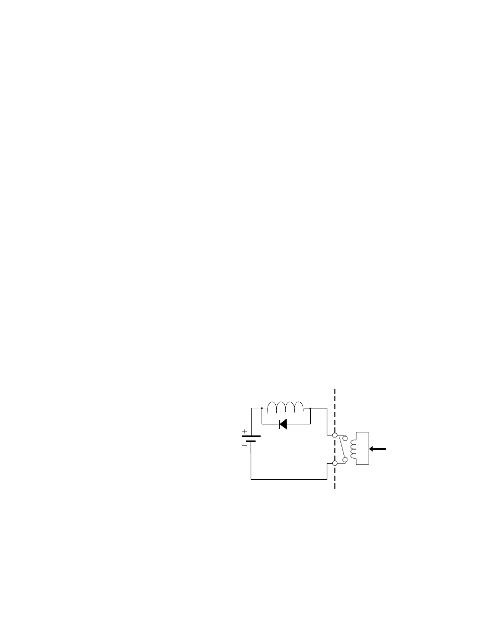
This situation can be improved for DC
inductive circuit loads by the addition of
external diode protection of the circuit. The
figure below illustrates diode protection. When
the contact is closed, the diode is reverse biased
and no current flows through it. When the
contact opens, current will continue to flow
through the inductive load. The diode provides a
path for current flow. The result that is the
energy is dissipated in the inductive coil and not
the relay contact.
Note : Do not use this circuit for AC loads.
Output module
isolation
From
OptiLogic
processor
Inductive load
Diode protection