Stuart Turner Showermate U1.8 bar Twin User Manual
Page 15
- 15 -
Cont ...
The wire which is coloured green and yellow must be connected to the terminal
in the connection unit which is marked with the letter E or by the earth symbol:
or coloured green or green and yellow.
The wire which is coloured blue must be connected to the terminal which is
marked with the letter N or coloured black.
The wire which is coloured brown must be connected to the terminal which is
marked with the letter L or coloured red.
4.21
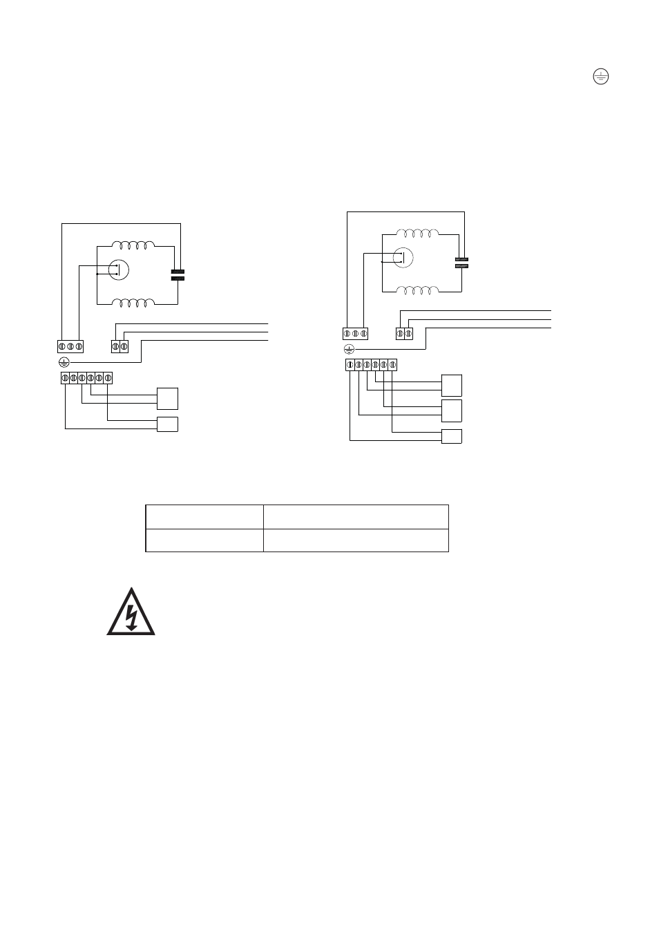
Wiring Diagrams:
Model
Fuse Size (AMPS)
All Models
5
4.22
Fuses: The following fuse size should be used with the appropriate pump.
4.23
Supply Cord Replacement:
The supply cord and internal wiring within the terminal box are
routed and secured to ensure compliance with the electrical
standard EN 60335-1. It is essential that prior to any disturbance
of this internal wiring, all cable routing and securing details are
carefully noted to ensure re-assembly to the same factory pattern
is always maintained.
If the supply cord is to be changed or is damaged, it must be replaced with a
special cord assembly available from Stuart Turner or one of their approved
repairers.
On disassembly note the cord retention and routing system. Re-assemble to the
same
pattern.
For information on cable connection consult the wiring diagram and cable gland
fitting
instructions.
MAIN WINDING
THERMOTRIP
CAPACITOR
START WINDING
FLOWSWITCH
REED (S3)
LINK
WIR
E (
BLUE)
BROWN
BL
ACK
GREEN / YELLOW
BLUE
BROWN
L
S2 S3 S3 S2
E
N 230 VAC/1PH/50Hz
SUPPLY
BLUE
N A M
N
L
S1
S1
PRESSURE
SWITCH (S1)
MAIN WINDING
THERMOTRIP
CAPACITOR
START WINDING
FLOWSWITCH
REED (S3)
LIN
K WIRE (BLUE)
BROWN
BLACK
GREEN / YELLOW
BLUE
BROWN
L
S2 S3 S3 S2
E
N 230 VAC/1PH/50Hz
SUPPLY
BLUE
N A
M
N
L
S1
S1
FLOWSWITCH
REED (S2)
PRESSURE
SWITCH (S1)
Single Pumps
Fig. 14
Twin Pumps
Fig. 15