Turning a rotor – MAHLE RTI BRC40 User Manual
Page 17
Page 16
RTI
RTI
RTI
RTI
TECHNOLOGIES, INC.
TECHNOLOGIES, INC.
TECHNOLOGIES, INC.
TECHNOLOGIES, INC.
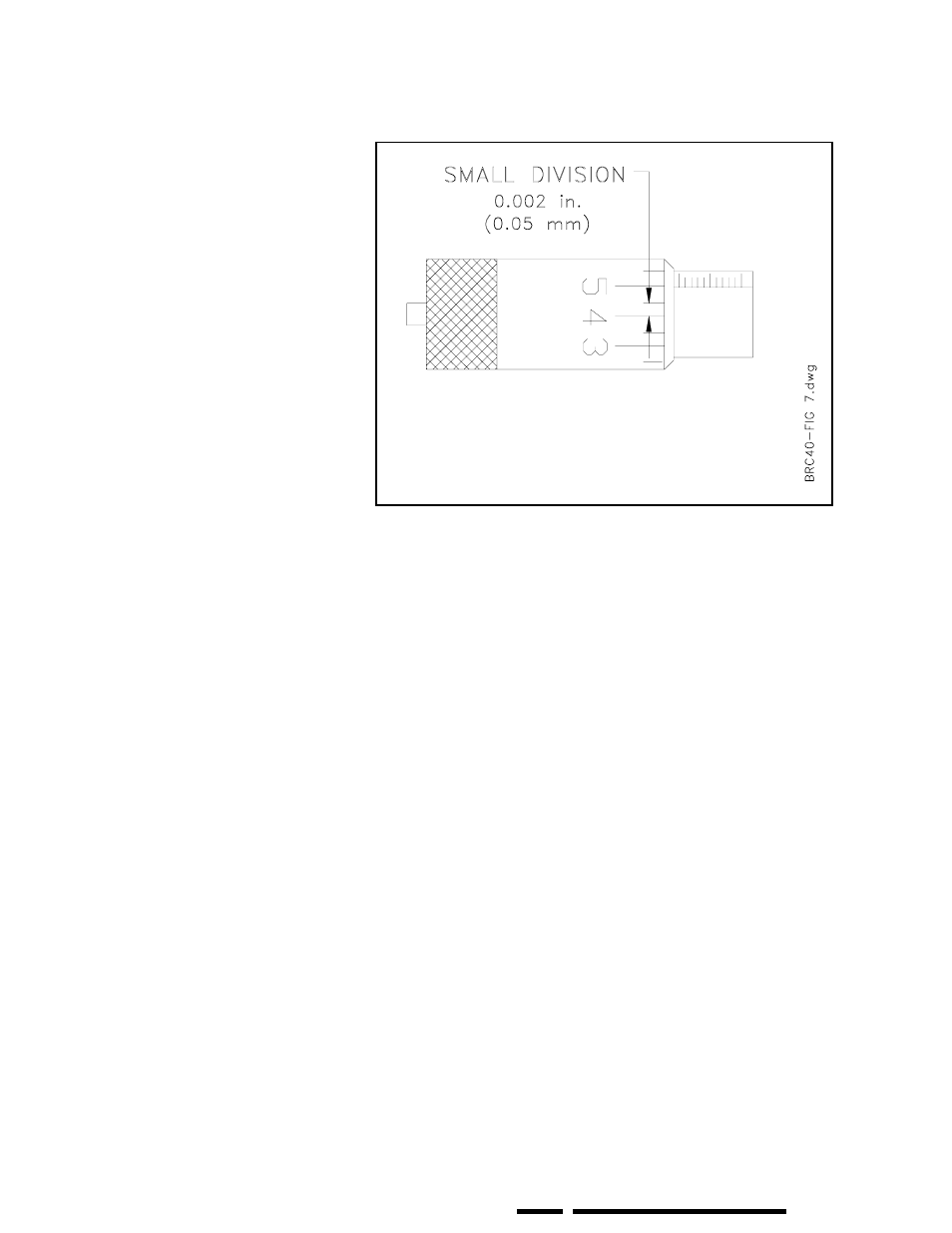
Figure 14 Cut Depth Micrometer
TURNING A ROTOR
18) When the cutting tools have moved
outward beyond the edge of the
rotor, press the bottom (OUTFEED)
of the Feed Direction Switch on the
lathe to place the switch in the OFF
position.
19) Momentarily turn off the Drive
Motor and check the surface of the
rotor. It should have a rough cut
surface across the entire face on both
sides. If not, make another rough cut,
otherwise proceed to the next step
for a finish cut.
20) Turn both Cut Depth Micro-meters
clockwise one small division to
move the cutting tool tips towards
the face of the rotor by 0.002 inch
(0.05 mm) Figure 14 illustrates that
0.002 inch is the distance between
two of the closest marks.
21) Turn the Feed Rate Switch on the
Drive Motor Control to 2 (slow
feed).
22) Press the top (INFEED) of the Feed
Direction Switch on the lathe. The
lathe cutting tools will automatically
feed inward making a finish cut on
the rotor. The cutting tools will
automatically stop at the setting
determined in Step 13 by setting the
Auto Infeed Stop button.
One rough cut and one finish cut are
normally sufficient for most applications.
If not, repeat rough and/or finish cuts as
required.
When a satisfactory surface finish has been obtained, press the
Safety Lock and move the AUTO/MAN Shift to MANUAL.
Back the cutting tool tips away from the rotor by turning the Cut
Depth Micrometers counter-clockwise.
Use the handwheel to back the cutting tools to a position beyond
the outer edge of the rotor.
Remove the Lathe and repeat the operation on the other side of
the vehicle.