Control devices – MAHLE RTI BRC40 User Manual
Page 14
RTI
RTI
RTI
RTI
TECHNOLOGIES, INC.
TECHNOLOGIES, INC.
TECHNOLOGIES, INC.
TECHNOLOGIES, INC.
Page 13
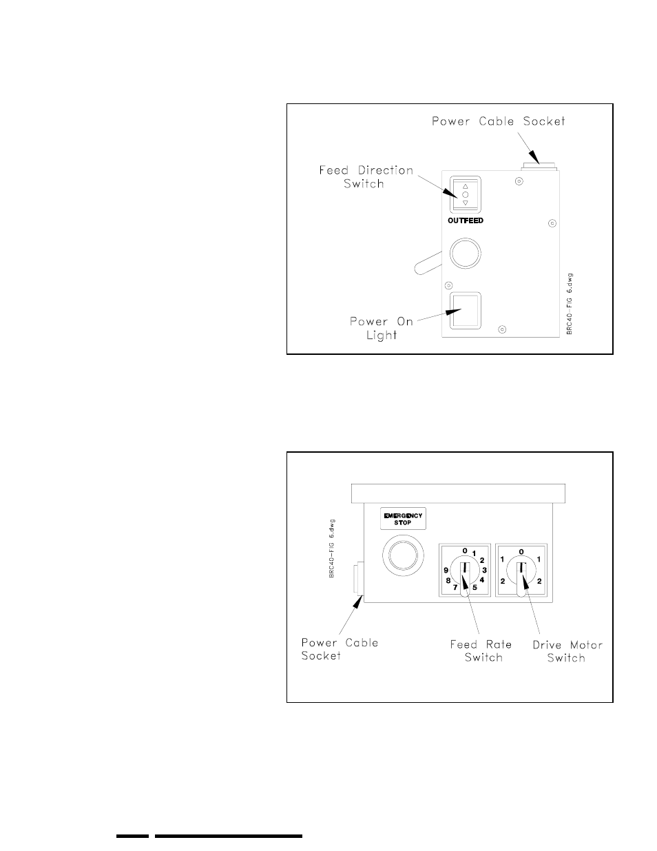
Figure 8 Lathe Controls
Figure 9 Drive Motor Controls
CONTROL DEVICES
FEED DIRECTION SWITCH
Direction of travel of the cutting tools is
controlled by a 3-position switch on the
Lathe Control Panel. Pressing the top
activates INFEED (towards the center of
the rotor) and pressing the bottom
activates OUTFEED (away from the
center of the rotor). Between these
positions is the OFF position.
INFEED STOP
This switch (See Item J on Page 8) stops
travel of the cutting tools when moving
towards the center of the rotor during
automatic operation.
POWER ON LIGHT
This light will be on when the lathe is
feeding in or out (Feed Direction Switch
pressed for INFEED or OUTFEED). The
brightness will vary depending on the
setting of the Feed Rate Switch (1 is dim,
9 is brightest).
The light will be OFF if the Infeed Stop is
pushed in all the way.
EMERGENCY STOP
The Emergency Stop Button stops the
Drive Motor and Lathe. Turn and pull
(See arrows on knob) to reset. Some
switches do not require turning.
FEED RATE SWITCH
Rate of travel (feed) of the cutting tools is
controlled by the variable Feed Rate
Switch on the Drive Motor Control Panel
(1 is slow, 9 is fast).
DRIVE MOTOR SWITCH
The Drive Motor turns the rotor
clockwise or counter-clockwise in one of
two speeds (1 is slow, 2 is fast). This 5-
position switch is located on the Drive
Motor Control Panel. The middle position
is OFF.