8. fail, 9. simulate, 11. input contacts – Yokogawa EXAxt SC450 4-Wire Analyzer for Conductivity/Resistivity User Manual
Page 36: 7. contact output setup
28
IM 12D08N05-01E
5-8. Fail
A fail contact is energized when a fail situation
occurs. Fail situations are configured in secton
5-12. For SOFT Fails the contact and the dis-
play on LCD are pulsating. For HARD Fails the
contact and the display on LCD are energized
continuously. Only contact S4 is programmed
as a fail-safe contact. This means that contact
S4 will be de-energized when a fail situation
occurs.
Hard Fail Only
The contact reacts to Hard Fails Only
Hard + Soft fail
The contact reacts to Hard and Soft Fails
5-9. Simulate
The contact can be switched on/off or a
percentage of output can be simulated. On/Off
enables the user to manually switch a contact
on or off. The percentage is an analogue value
and represents the on time per period. The
Duty Cyde Period time (see figure 5-4) is used
as a period for percentage simulation. Note that
the (simulated) settings of the contacts become
visible in measuring mode and after HOLD has
ended c.q. has been overruled. A warning is
activated in case of a simulated output contact.
5-10. Water for Injection Monitoring
(USP 645 and EU 0169).
Setting up EXA SC450 for WFI monitoring
1. A function “USP limit exceeded” is defined
as an error code on sec. 5-12, Errors 2/3.
This can be set to off/warn/fail according
to your requirement. This function can
be modified by the function “USP safety
margin” in %. This is a percentage
of the WFI conductivity value at that
temperature that serves as safety margin.
This is independent of what is being
measured. The display shows this error
when the water quality exceeds the WFI
conductivity limits as set in stage 1.
2. We have introduced uncompensated
conductivity in the DISPLAY menu. In the LCD
display the user can read the temperature
and the raw conductivity to compare his water
quality with the WFI table.
3. We have added a USP function to the
contact allocation. The contact output S1
can be selected as USP alarm if the function
“USP limit exceeded” has been selected.
The contact closes when the USP limit is
reached.
0.0
0.5
1.0
1.5
2.0
2.5
3.0
3.5
μS/cm
USP
Safety
Margin
25
50
75
100
˚C
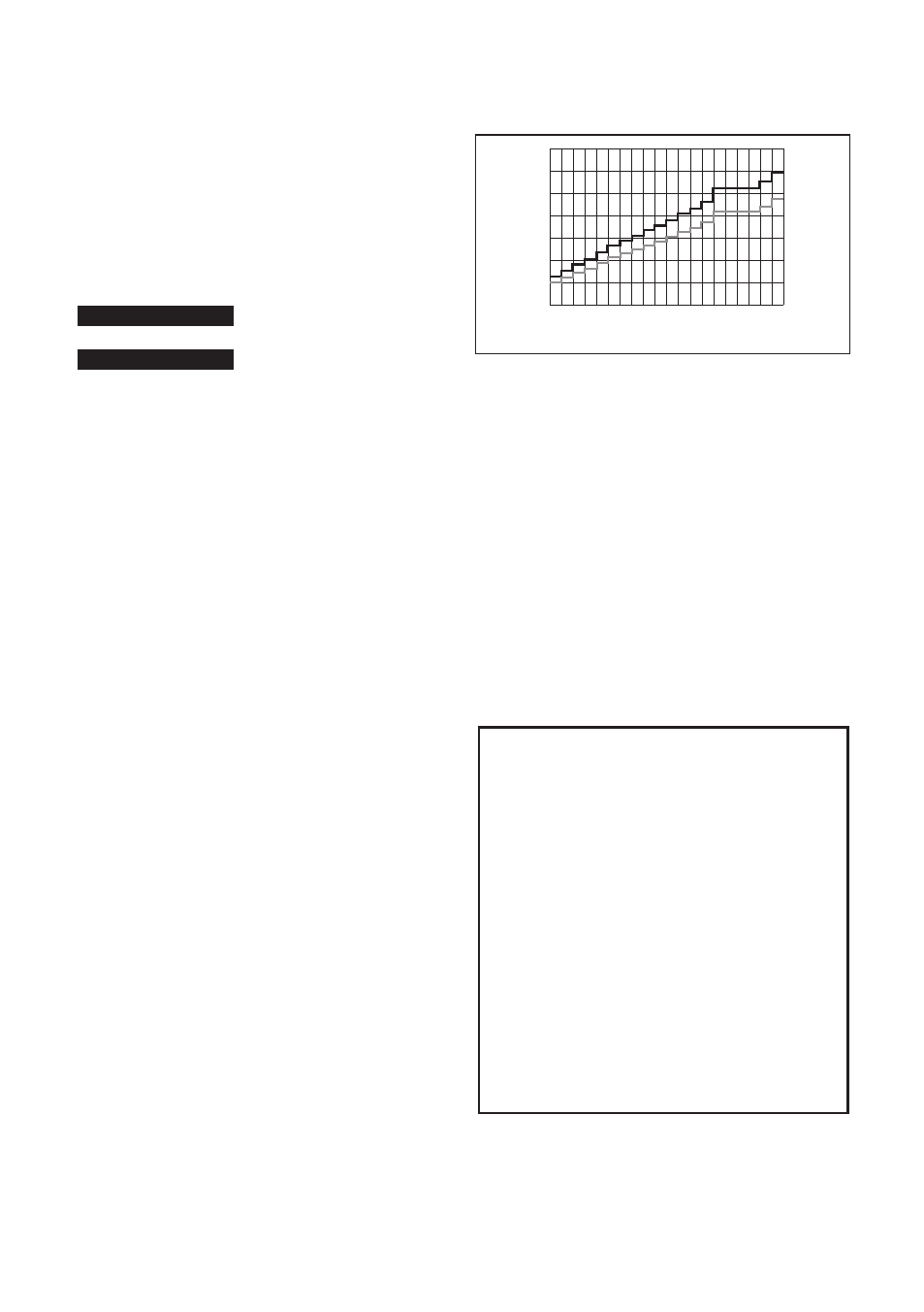
Figure 5-6. USP Safety Margin
Limit of uncompensated conductivity as function
of temperature as defined for WFI. USP safety
margin set as 20 % will close the contact at 80 %
of the conductivity value at all temperatures.
For example, if the temperature is 64 ºC. and
the safety margin is adjusted for 20%, then the
contact closes at 0.8 x 2.2 μS/cm. = 1.76 μS/cm.
(2.2 μS/cm is the WFI limit at 64ºC). In resistivity
mode the contact will close at an uncompensated
resistivity of 1/1.76 μS/cm. = 0.568 Mohm.
Recommended Commissioning settings when
monitoring WFI in a > 80 ºC WFI installation.
Commissioning
Measurement Set up
Measure
Conductivity only
Temp Compensation
automatic
Conductivity 1
None
Error Configuration (Errors 2/3)
USP limit exceeded
Warn
Output Setup
S1
USP
USP safety margin 10 %
S2
Alarm
Parameter
Temperature
Setpoint
80 C
Direction
Low
Delay Time
0.2 s
Expiry Time
0 (disabled)
5-11. Input contacts
The terminal of the SC450G provides for an in-
put contact (see Figure 3-7). This input contact
can be used to switch the range of the outputs.
The range can be increased by 1 decade.
This is available for only mA1 output.