6. wiring of sensors – Yokogawa EXAxt SC450 4-Wire Analyzer for Conductivity/Resistivity User Manual
Page 20
12
IM 12D08N05-01E
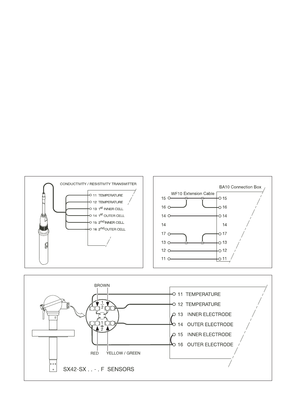
Figure 3-9. Sensor wiring diagrams
3-6. Wiring of sensors
General precautions
Generally, signals from sensors are at low volt-
age and current level. Thus a lot of care must
be taken to avoid interference. Before connect-
ing sensor cables to the converter make sure
that following conditions are met:
– the sensor cables are not mounted in
tracks together with high voltage and or
power switching cables
– only standard sensor cable or extension
cable is used
– the converter is mounted within the dis-
tance of the sensor cables (max. 10 m) +
up to 60m WF10 extension cable.
– the setup is kept flexible at the sensors end
for easy insertion and retraction of the sen-
sor in the fitting.
Sensor wiring
Refer to figure 3-9, which includes drawings
that outline sensor wiring.
The EXAxt can be used with a wide range of
sensor types. The sensor system fall into two
categories, the ones that use fixed cables and
the ones with separate cables.
To connect sensors with fixed cables, simply
match the terminal numbers in the instrument
with the identification numbers on the cable
ends.