3 wiring the sensor, 1 ph measurement, Wiring the sensor 1.3.1 – Yokogawa 2-Wire Dual Channel Transmitter/Analyzer FLXA21 User Manual
Page 5: Ph measurement
<1. Wiring and Installation>
3
IM 12A01A02-12E
4th Edition : Sep. 3, 2013-00
1.3
Wiring the sensor
The FLXA21 can be used with a wide range of commercially available sensor types, both from
Yokogawa and other manufacturers. For more detailed information, refer to the respective
instruction manual of the sensor. The sensor systems from Yokogawa fall into two categories; the
ones that use a fixed cable and the ones with separate cables.
To connect sensors with fixed cables, simply match the terminal numbers in the instrument
with the identification numbers on the cable ends. The separate sensors and cables are not
numbered, but instead use a color-coding system.
1.3.1
pH Measurement
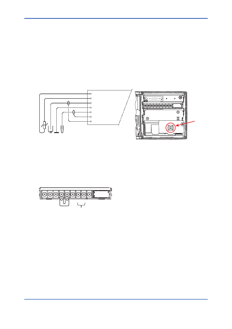
Conventional pH sensors are connected to the module as follows:
11 Temperature
12 Temperature
13 Reference
14 Solution ground
15 Glass (measure)
16 Shield
17 Shield
FLXA21
REF
TC
PH
Liquid
Earth
In addition to the wiring of the sensor, insure that a jumper for low-impedance sensor inputs is
installed. The jumpers can be found on the plastic sensor module cover and can be stored in the
lower level module wiring cover.
• pH Glass Electrode is a high impedance sensor input
• Special electrodes using 2 glass sensor (example: Pfaudler, SC24V) do not need jumpers.
Terminals 15-16 are identified as input 1 (High Impedance) and terminals 13-17 are defined as
input 2 (Low Impedance). For conventional pH sensors, the jumper is placed as illustrated:
16
15
19
17
13
18
14
12
11
PH
Input 1
Input 2
Glass sensor on Input 1.
Reference sensor on Input 2.
Jumper
holder