Appendix, Uappendix, A2.1 – Yokogawa 2-Wire Dual Channel Transmitter/Analyzer FLXA21 User Manual
Page 17
15
IM 12A01A02-12E
4th Edition : Sep. 3, 2013-00
u
Appendix
install the cable glands.
CAUTION
inches). Unused cable entry holes must be sealed with cable glands including the supplied close
up plugs.
(A hole is drilled, if specified.)
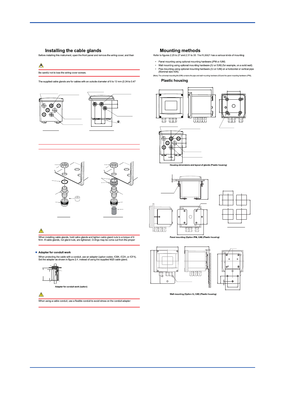
Plastic Housing
Stainless Steel Housing
F0202.ai
(For sensor 2 cable)
For sensor 1 cable
For power supply
For grounding cable
Figure A.1
Cable gland diagram
A1
137
22.2
44
(For sensor 2 cable)
For sensor 1 cable
For power supply
25.3
26.5
DANGER
positions.
Adapter
49
(1.93
"
)
G1/2 screw (/CB4), 1/2 NPT screw (/CD4)
M20x1.5 screw (/CF4)
Approx.
55(2.2
"
)
Packing
Unit: mm(inch)
Nut
F0204.ai
DANGER
The stress on the conduit adapter may damage the housing.
CAUTION
Be careful not to be injured by the sharp hole edges on the housing.
Install the supplied cable gland as shown in Figure 2.4. When using an adapter for conduit work,
see Figure 2.5.
F0203.ai
Cable gland nut
O-ring
Gable gland
Sleeve
(for grounding cable line
of the plastic housing)
Plastic Housing
Cable gland cap
Cable gland nut
Gaskets
Washer
Stainless Steel Housing
Gable gland
Cable gland cap
Rubber plug
(without wiring)
Figure A.2
Cable glands
The unused cable glands should be sealed with the supplied close up plug.
Figure A.3
capabilities.
144
80
80
144
22.5
141
151
137
20.2
44.9
26.5
24.7
26.5
1
137
(For sensor 2 cable)
For sensor 1 cable
For power supply
For grounding cable
4-M6 depth 5
Uit: mm
A2
A2.1
Figure A.4
2-M5 length 35
185
178
100
195
135
Panel thickness
1 to 12
Spacing panel cutout
4-M6 *
138
+1
0
138
+1
0
FB4_03.ai
Unit: mm
*: Tighten the four screws to a torque of 2 N•m.
144
164
13
100
70
144
224
200
50
15
For wall mounting
3-ø10 holes
4-M6 *
FB4_02.ai
Unit: mm
*: Tighten the four screws to a torque of 2 N•m.
Figure A.5
Figure A.6