2 wiring the power supply, Wiring the power supply – Yokogawa 2-Wire Dual Channel Transmitter/Analyzer FLXA21 User Manual
Page 4
<1. Wiring and Installation>
2
IM 12A01A02-12E
4th Edition : Sep. 3, 2013-00
1.2
Wiring the power supply
FLXA21 is a 2-wire transmitter and can be powered by a DC power supply of max. 40 VDC. The
Power Supply voltage depends on:
• The load resistance: impedance of electronic equipment: typically 250 Ohm
• Number of input modules: 1-sensor measurement or 2-sensor measurement.
One (1) Sensor module (1 input):
16 to 40 V DC (for pH/ORP, SC and DO)
17 to 40 V DC (for ISC)
21 to 40 V DC (SENCOM pH/ORP)
Two (2) Sensor modules (2 inputs):
22.8 to 40 V DC (for pH/ORP, SC and DO)
250
600
1000
0
24.7
18
V - 11.5
0.022
R =
1295
1617
22.8
40
40
Voltage (V)
2-sensor measurement
Load resistance (Ω)
Digital Communication
Range (HART)
250
304
600
516
1000
0
24.7
18
V - 11.5
0.022
R =
1295
17
40
22.86
40
Except SENCOM
Voltage (V)
Load resistance (Ω)
Digital Communication
Range (HART)
18.2 21
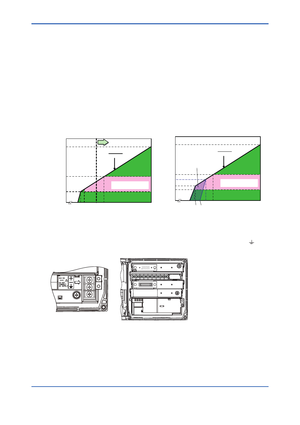
Figure 1 Supply Voltage and Load Resistance for
pH/ORP (analog sensor), SC and DO
Figure 2 Supply Voltage and Load Resistance for
ISC and pH/ORP SENCOM sensor
The power supply is connected to the terminals marked with + and – which corresponds with the
polarity of the DC power supply. The shield/ ground is connected to the terminal marked ,
then replace ground wiring cover.