Warning – Yokogawa 2-Wire Dual Channel Transmitter/Analyzer FLXA21 User Manual
Page 11
<1. Wiring and Installation>
9
IM 12A01A02-12E
4th Edition : Sep. 3, 2013-00
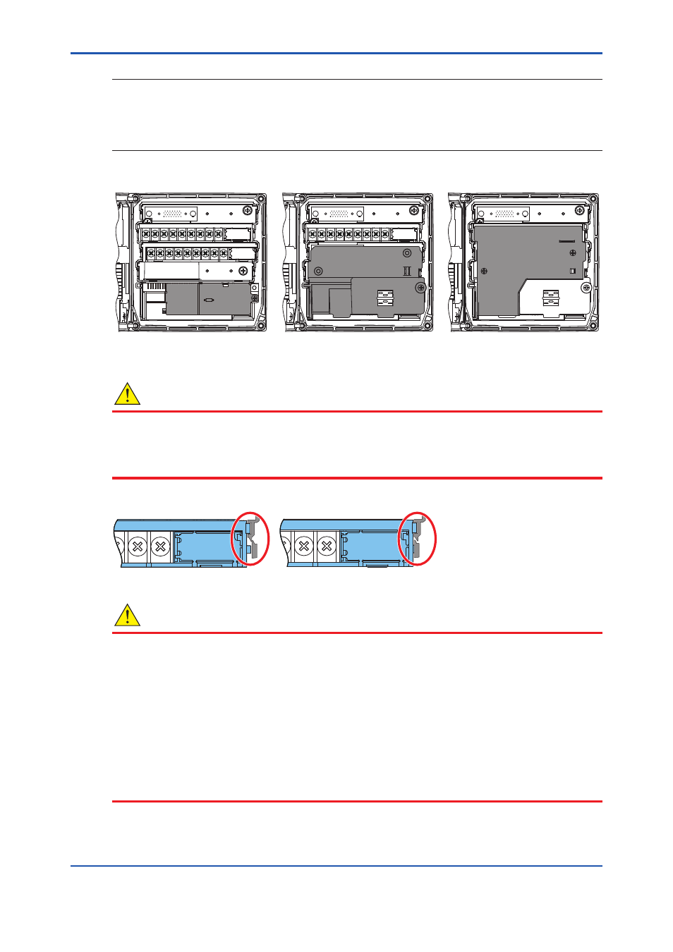
NOTE
When two sensor modules are used, the upper-level module is for input 1 and the lower-level
module is for input 2. For ease of installation, first wire input 2 sensor on the lower-level module
(A), and attach the wiring cover; then wire input 1 sensor on the upper-level module (B) and
replace the module wiring cover (C).
(A)
(B)
(C)
When all wiring is completed and all covers have been installed, the front cover can be closed
and the power can be switched on.
WARNING
When one of the modules has been removed and replaced, make sure you lock the module
securely in place. Confirm that all locking-tabs (including for BLANK slots) are in “Locked”
position before you close the front panel. If the locking-tabs are in “Unlock” position, the front
panel may be interfered with locking-tabs.
Unlock
Lock
WARNING
Do not tighten up four front panel screws one by one.
Each front panel screw should be tightened up in two times of screwing. And, firstly the screw
at the upper left should be screwed a bit, the next is at the lower right, third is at the upper right,
and fourth is at the lower left. The second round is the same sequence again to tighten up four
screws.
Do not use an electric screwdriver with high revolutions. If an electric screwdriver is used for
these front panel screws, the revolutions of the electric screwdriver should be less than 400 rpm.
Four screws should be tightened to the following torque;
0.8 to 0.9 N•m (for the plastic housing)
1.5 to 1.6 N•m (for the stainless steel housing)