2 tiis intrinsically safe type, 6 installation of flameproof type, 1 tiis flameproof type – Yokogawa PK200 User Manual
Page 8: Tiis intrinsically safe type -3, Installation of flameproof type -3, Tiis flameproof type -3
IM 21B03D01-01E
1-3
1. HANDLING PRECAUTIONS
3. Installation
• Control equipment connected to barrier must not use
or generate more than 250 Vrms or Vdc.
• The safety barrier must be CSA certified.
• Associated apparatus manufacturer’s installation
drawing must be followed when installing this
apparatus.
• The maximum power delivered from the barrier
must not exceed 0.9 W.
• Note a warning label worded “SUBSTITUTION OF
COMPONENTS MAY IMPAIR INTRINSIC
SAFETY” and “INSTALL IN ACCORDANCE
WITH DOC. NO. ICS006-A12 P.1 AND 2”.
1.5.2 TIIS Intrinsically Safe Type
The model PK200/JS3 current-to-pneumatic converters,
which have obtained certification according to techni-
cal criteria for explosion-protected construction of
electric machinery and equipment (Standards Notifica-
tion No.556 from the Japanese Ministry of Labor)
conforming to IEC standards, is designed for hazardous
areas where explosive gases and/or inflammable vapors
may be present. (This allows installation in Division 0 ,
1 and 2 areas)
To preserve the safety of flameproof equipment
requires great care during mounting, wiring, and
piping. Safety requirements also place restrictions on
maintenance and repair activities. Users absolutely
must read the following instructions and “Installation
and Operating Precautions for TIIS Intrinsically Safe
Equipment (EX - A03E)” at the end of this manual.
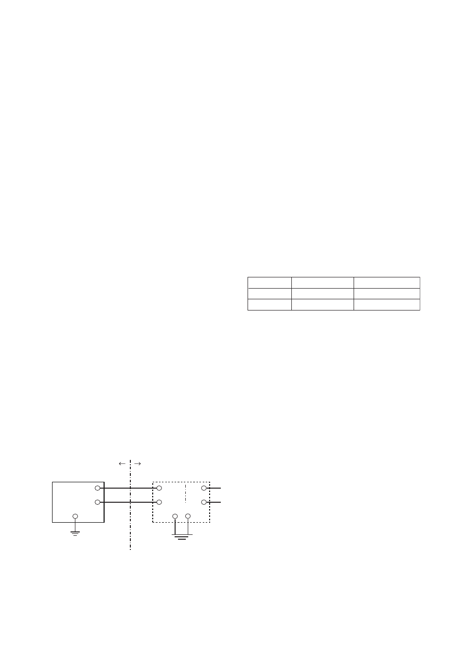
1. Installation
The PK200 Current-to-Pneumatic Converter should be
used in connection with the certified safety barrier as
shown below. All wiring shall comply with local
installation requirements.
Hazardous Area
Non-hazardous Area
+
–
+
–
+
–
PK200 Current-to-pneumatic
Converter
Safety barrier
[Installation Diagram]
F0107.EPS
2. Temperature
Install the PK200, So that any part of the instrument
that may exposed to the inflammable gas or vapor
would not exceed the temperature 60
°C
3. Safety Barrier
Use the certified safety barrier that satisfies the
following requirements.
• Safety Ratings
Maximum output voltage: 28V or less
Maximum output current: 94.3mA or less
Maximum output power: 0.66W or less
• Protection type and group
Protection type: ia Group: IIC
• Allowable inductance and capacitance
Maximum_external inductance: More than the
external wiring inductance
Maximum_external capacitance: More than the sum
of the external wiring capacitance and 39nF
Table 1.1
Recommended Safety Barrier
Contact each supplier for the details of the barrier.
T0101.EPS
Supplier
Type
Model
MTL
Isolated type
MTL5046
P+F
Isolated type
KFD2-SCD-Ex1.LK*
* To connect this barrier with PK200 converter, for
the connection between the barrier and the control-
ler, use the terminal #7 and #9 of the barrier.
1.6 Installation of Flameproof
Type
1.6.1 TIIS Flameproof Type
The model PK200/JF3 current-to-pneumatic converters,
which have obtained certification according to techni-
cal criteria for explosion-protected construction of
electric machinery and equipment (Standards Notifica-
tion No.556 from the Japanese Ministry of Labor)
conforming to IEC standards, is designed for hazardous
areas where explosive gases and/or inflammable vapors
may be present. (This allows installation in Division 1
and 2 areas)
To preserve the safety of flameproof equipment
requires great care during mounting, wiring, and
piping. Safety requirements also place restrictions on
maintenance and repair activities. Users absolutely
must read “Installation and Operating Precautions for
TIIS Flameproof Equipment (EX - B03E)” at the end
of this manual.