Yokogawa PK200 User Manual
Page 25
IM 21B03D01-01E
6-3
6. MAINTENANCE
(7) Pull out the amplifier directly, taking care not to
bend the zero adjustment control.
(8) Remove the silicon tube left in the case.
Mounting the Amplifier
(1) Insert the accessory silicon tube into the body cap
firmly.
F0608.EPS
Tube pin on case
Figure 6.8 Silicon Tube Case Cap
CAUTION
Be sure to use the accessory silicon tube that
comes with the amplifier for replacement. Note
that the tube size varies depending on the
amplifier to be used. Be sure to use the proper
tube to prevent air leakage and precision dete-
rioration.
(2) Adjust the angle so that the volume knob of zero
adjustment forms a right angle with the amplifier.
F0609.EPS
Volume Knob of zero point adjustment
Figure 6.9 Zero Adjustment Control
(3) Pass the silicon tube through an amplifier hole and
mount the amplifier directly so that the sleeve of
the pressure sensor leads into the hole of the case.
NOTE
1.Do not apply undue pressure to the pressure
sensor.
2.Do not bend the zero adjustment volume knob
to prevent it from contacting the zero adjust-
ment set screw.
(4) Fasten the four set screws for fixing the amplifier
(see Figure 6.7).
(5) Connect the four wires in the order of yellow
(ACT+), white (ACT-), red (IN+) and black (IN-).
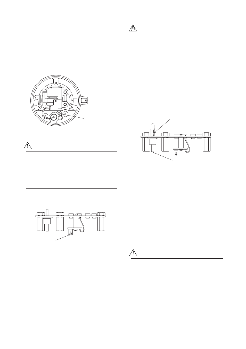
(6) Insert the silicon tube into the amplifier pressure
sensor firmly.
F0610.EPS
Silicon tube
Pressure sensor
Figure 6.10 Pressure Sensor and Silicon Tube
(7) In a model allowing 4-20/10-50mA selection, refer
to 5.5 to set the socket switch as necessary.
(8) Mount the amplifier cover.
Inspection after Amplifier Replacement
After replacing the amplifier, perform the insulation
resistance test and withstand voltage test. Be sure to
perform them according to the following procedure,
referring to the corresponding tester instruction
manuals.
CAUTION
(1) Overvoltage of the test voltage that is so
small that it does not cause an dielectric
breakdown may in fact deteriorate insulation
and lower the safety performance; to prevent
this it is recommended that the amount of
testing be kept to a minimum.
(2) The voltage for the insulation resistance test
must be 500V DC or lower, and the voltage
for the withstand voltage test must be 500V
AC or lower. Failure to heed these guidelines
may cause faulty operation.