Troubleshooting, 1 overview, 2 operation principle – Yokogawa PK200 User Manual
Page 27: Troubleshooting -1, Overview -1, Operation principle -1
IM 21B03D01-01E
7-1
7. TROUBLESHOOTING
7.
TROUBLESHOOTING
7.1 Overview
If the PK200 converter does not operate normally,
check the condition carefully and solve any problem in
accordance with section 7.3 Troubleshooting Flow.
If problem appears difficult to correct, consult
YOKOGAWA service personnel.
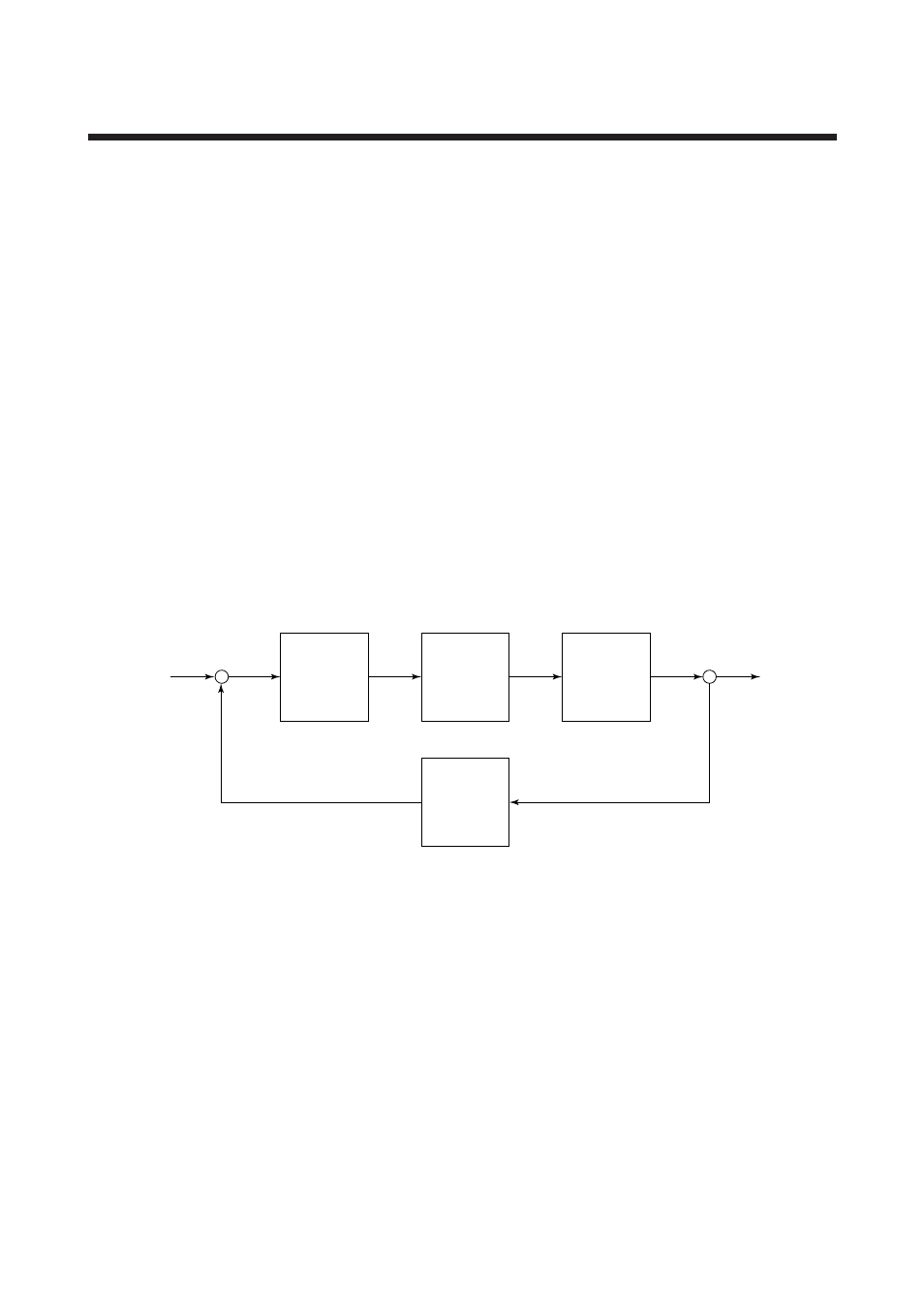
7.2 Operation Principle
The PK200 current-to-pneumatic converter accepts a 4
to 20mA or 10 to 50mA current signal from an
electronic controller as an operating signal. This signal
is input to a torque motor via an electric circuit,
generating a torque proportional to the current signal.
Torque
motor
Voltage
Voltage
–
+
4 to 20mA
input
20 to 100 kPa
Output
Nozzle
flapper
Pressure
sensor
Pilot relay
Position
Air
pressure
Air
pressure
F0701.EPS
Figure 7.1 PK200 Current-to-Pneumatic Converter Operation Principle Diagram
An increase in the input signal causes the flapper at the
end of the torque motor moving piece to move in the
nozzle closing direction. When the nozzle is closed,
back pressure increases, displacing the input diaphragm
inside the control relay. This causes the control relay
output air pressure to increase.
This output air pressure is output as PK200 converter
output pressure and is also input to a feedback pressure
sensor. The sensor then converts the pressure input into
an electric signal, which is fed back to the electric
circuit. The signal is then compared with the manipu-
lated output signal, the result of which activates
modification action until an output air pressure
balanced with the input signal is obtained.
In this way, an output air pressure proportional to the
input signal, which is a manipulated output signal, is
obtained.