Operation, 1 auto/manual (a/m) transfer mechanism, 2 zero point adjustment – Yokogawa PK200 User Manual
Page 19: Operation -1, Auto/manual (a/m) transfer mechanism -1, Zero point adjustment -1
IM 21B03D01-01E
5-1
5. OPERATION
5.
OPERATION
5.1 Auto/Manual (A/M) Transfer
Mechanism
Please refer to following instruction for the model with
A/M selector switch (optional code: /AM).
For the model without A/M selector switch, please go
to section 5.2.
Use of A/M transfer mechanism requires that a supply
pressure adjusting reducing valve be installed.
(1) Set the A/M selector switch provided at the front
(on the supply air pressure gauge side) of the
converter to “M.” (Turn the switch clockwise.)
(2) This allows supply air pressure to be output, which
is supplied to the control valve.
(3) Output air pressure can be regulated using the
pressure regulator. Because the output pressure is
not same as supply pressure, it is necessary to
adjust it watching an output pressure gauge
attached to this instrument. Pressure gauge mini-
mum unit is 10kPa (standard output type) or 20kPa
(doubled output type).
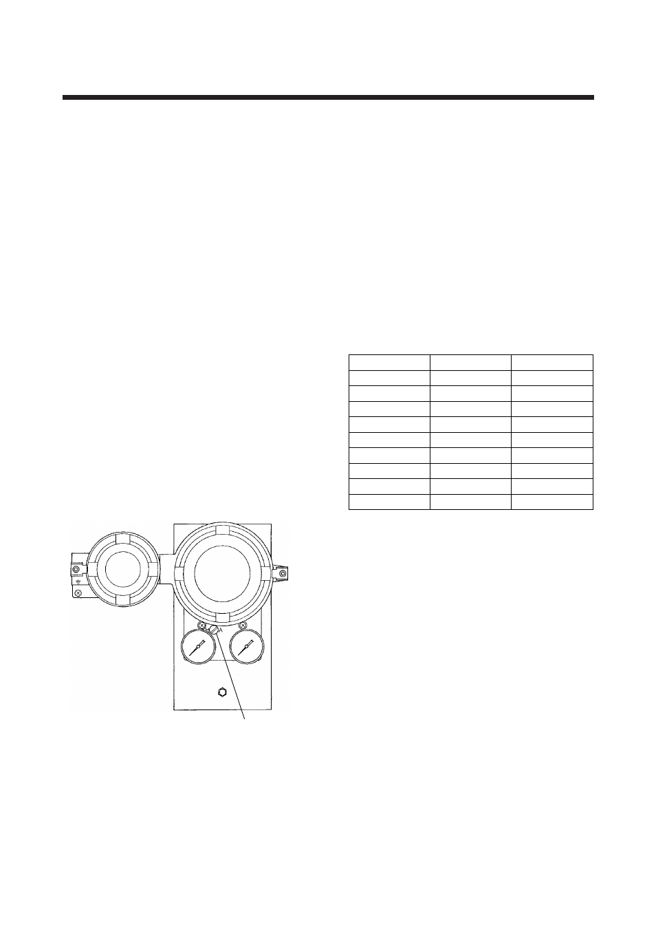
A/M selector switch
F0501.EPS
Figure 5.1 Auto/Manual Transfer Mechanism
5.2 Zero Point Adjustment
(1) For the model with A/M selector switch, please set
the A/M selector switch to A (Auto). (Turn the
switch counterclockwise.)
(2) Apply supply air pressure to the current-to-
pneumatic converter.
For supply air pressure, see the data plate or Table
5.1 “Supply Air Pressure.”
Standard output applies for model suffix output
signal code “1, 3, 5, 7” and multiplied pressure
output for model suffix output signal code “2, 4, 6,
8, 9.”
Table 5.1 Recommended Supply Air Pressure
Output Signal Code
Output Signal
Supply Air Pressure
1
20 to 100kPa
130 to 150kPa
2
40 to 200kPa
230 to 260kPa
3
0.2 to 1.0kgf/cm
2
1.3 to 1.5kgf/cm
2
4
0.4 to 2.0kgf/cm
2
2.3 to 2.6kgf/cm
2
5
0.2 to 1.0bar
1.3 to 1.5bar
6
0.4 to 2.0bar
2.3 to 2.6bar
7
3 to 15psi
19 to 22psi
8
6 to 30psi
34 to 37psi
9
3 to 27psi
34 to 36psi
T0501.EPS
(3) Then input an input signal.
Input a 0% electric signal.
Apply 4mA for 4 to 20mA input or 10mA for 10
to 50mA input.
(4) Make zero point adjustment so that the output air
pressure reaches the specified pressure.
For output air pressure, see the data plate or Table
5.2 “Output Signals.”
To increase output air pressure, turn the zero
adjustment clockwise. To decrease the pressure,
turn the zero adjustment counterclockwise. (See
Figure 5.2.)
For the model with reverse action (/RA), please
turn zero adjustment counterclockwise to increase
output air pressure. To decrease output air pres-
sure, please turn zero adjustment clockwise.