4 disassembly and assembly, Disassembly and assembly -2, Caution – Yokogawa Wireless Temperature Transmitter YTA510 User Manual
Page 53: Important
<8. Maintenance>
8-2
IM 01C50E01-01EN
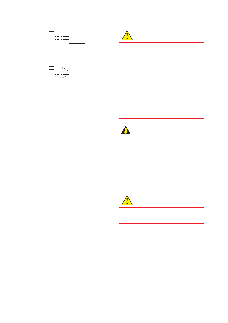
Example of wiring for thermocouple or DC voltage input
F0801.ai
DC voltage generator
1
2
3
4
5
Example of wiring for RTD 4-wire type
Variable resistor
1
2
3
4
5
(B)
(B)
(A)
(−)
(A)
YTA sensor
input terminal
YTA sensor
input terminal
(+)
Figure 8.1
Example of wiring for calibration
equipment
4) Calibration Procedure
a) For DC voltage input
With a voltage generator, deliver input
signals corresponding to 0, 25, 75, or
100% of the input span to the temperature
transmitter.
b) For thermocouple input
Since this instrument is equipped with a cold
junction compensating function, use a cold
junction compensating function in universal
calibrator in order to compensate for this
function upon calibration. According to the
reference millivolt table for thermocouple,
obtain millivolt corresponding to 0, 25, 50,
75, or 100% of the span, and use that power
as the input value, then deliver it from the
universal calibrator to the temperature
transmitter. Check the output value for that
input value.
c) For resistance thermometer (RTD) input
Using a thermometer resistor as input,
calibration of the temperature transmitter
is carried out via a 4-core wire connection.
As defined in the reference resistor value
table of the resistance thermometer (RTD),
obtain resistance values corresponding to
0, 25, 50, 75 or 100% of the span, and use
the obtained resistance as the input value,
then deliver it to the temperature transmitter
by means of a variable resistor. Check the
output value for that input value.
Apply a specified input signal following steps
a) to c) above. If the output signal is outside
the accuracy range, perform output adjustment
using the device configuration tool. For
details on how to perform adjustment, refer to
subsection 7.3.13 Input calibration.
8.4 Disassembly and Assembly
CAUTION
Precautions for the intrinsic safety explosion
prevention type instrument
Intrinsic safe type transmitters must be, as
a rule, removed to a non-hazardous area
for maintenance and be disassembled and
reassembled to the original state. Check the
insulation, and execute Insulation Test, when it
is disassembled and reassembled to the original
state.
Refer to section 2.7 “Insulation Resistance and
Dielectric Strength Test” for details of Resistance
Test.
Refer to "Precautions for the intrinsic safety
explosion prevention type instrument" in the end
of this manual of details.
IMPORTANT
• Perform the provisioning when replacing the
RF assembly. Refer to 6.4 Connecting to the
Field Wireless Network for details.
• Replace the batteries and perform the
parameter settings when replacing the CPU
assembly. Refer to 8.4.5 Replacing the
Batteries.
This section describes procedures for disassembly
and reassembly for maintenance and component
replacement.
CAUTION
Always remove the battery pack and shut off
before disassembly. Use proper tools for all
operations.