Component names, Component names -1 – Yokogawa EJX530B User Manual
Page 19
<3. Component Names>
3-1
IM 01C27F01-01EN
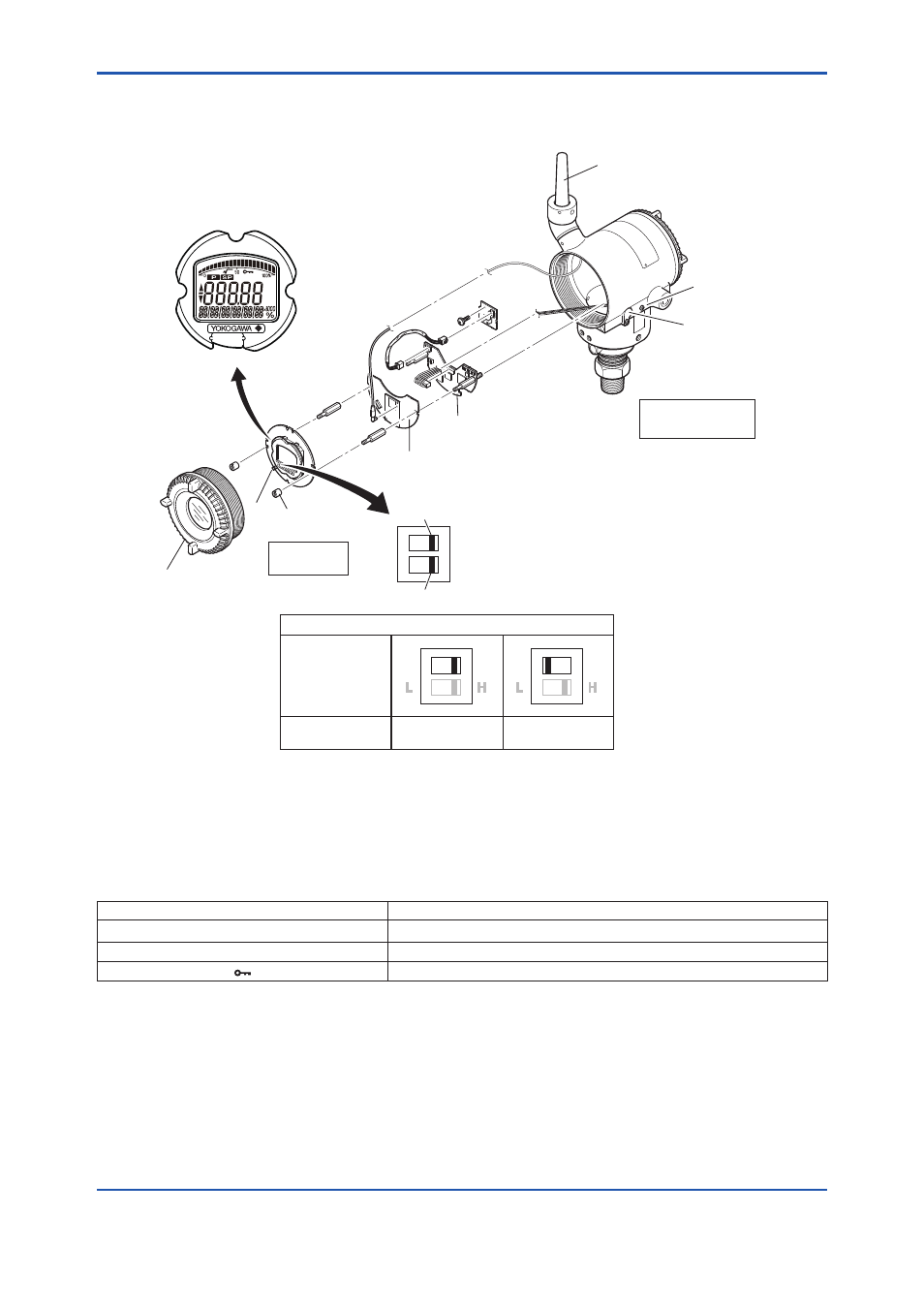
3. Component Names
F0301.ai
YES
(Note 2)
(Write disabled)
NO
(Write enabled)
Zero-adjustment
screw
Ground terminal
RF assembly
CPU assembly
Transmitter
section
Amplifier Cover
Mounting
screw
Integral
indicator
Hardware write protection switch (WR)
Write Protection
Write Protection
Switch Position
(Note 1)
Pressure-detector
section
Slide
switch
E WR
D
Not in use
Write protection switch
H
L
E
D
H
L
E
D
Antenna (Note 3)
Note 1: Set the switch as shown in the figure above to set the write protection. The hardware write protection switch is set to E side. Set
to H side for the switch of not-in-use.
Note 2: When the switch is D side (write protection setting), provisioning is acceptable. For details of provisioning, refer to section 7.4 “
Connecting to the Field Wireless Network “.
Note 3: The detachable antenna is applied when the amplifier housing code 7 or 8 is specified.
Figure 3.1
Component Names
Table 3.1
Display Symbol
Display Symbol
Meaning of Display Symbol
▲
The output signal being zero-adjusted is increasing.
▼
The output signal being zero-adjusted is decreasing.
Write protect function is enabled.