8 output signal low cut mode setup, 9 impulse line connection orientation setup, 10 integral indicator display mode – Yokogawa EJX430B User Manual
Page 57: Output signal low cut mode setup -19, Impulse line connection orientation setup -19, Integral indicator display mode -19
<8. Setting Parameters>
8-19
IM 01C27B01-01EN
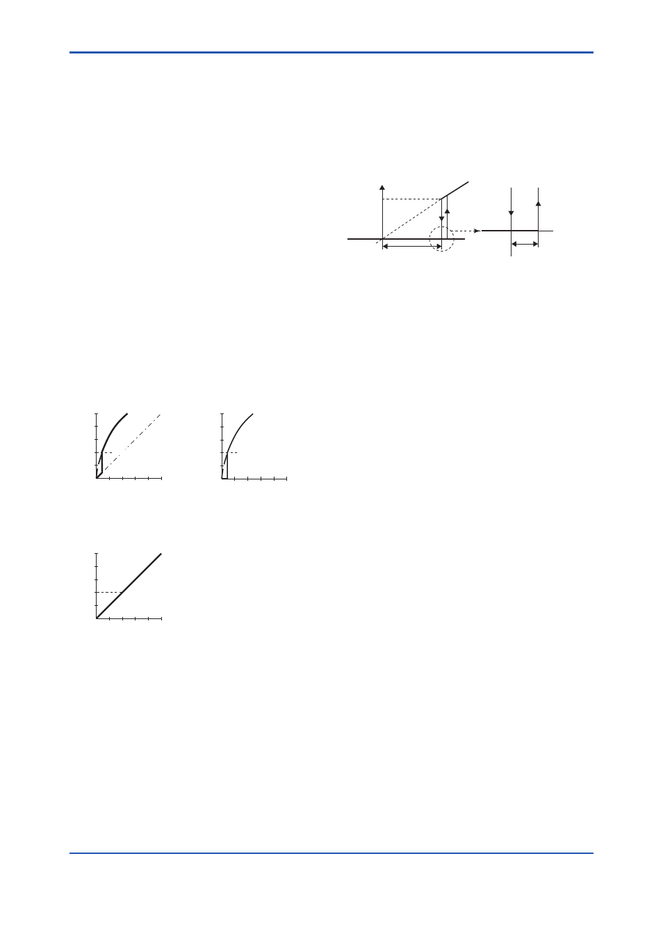
8.3.8 Output Signal Low Cut Mode Setup
Low cut mode can be used to stabilize the output
signal near the zero point.
( There is 10% of hysteresis at only point of
transition from low to high)
[Setup Low Cut Value]
• Procedure to call up the Lower cutoff* display
AI1 block: Lower cutoff*
Example: setup LOW_CUT of output to 15%
Lower cutoff*
= (“Eu at 100%” - “Eu at 0%”) × 0.15 + “Eu at 0%”
*: “Low Cutoff” is used instead of “Lower cutoff” for
Detachable antenna type (Amplifier housing code: 8 or
9).
[Setup Low Cut Mode]
• Procedure to call up the Low Cut Mode display
AI1 block: Low Cut Mode
Example: Low cut at 20%
(%)
50
20
0
50 (%)
For low cut in Linear mode
For low cut zero mode
[ sq root output ]
Example: Low cut 20%
Input
(%)
50
20
0
50 (%)
Example: Low cut 20%
F0804.ai
(%)
50
20
0
50 (%)
For low cut in Linear mode
[ Linear output ]
Example:
Low cut 20%
Output
Output
Input
Input
Output
Figure 8.3
Low Cut Mode
The low cut point has hysterisis so that the output
around the point is behaved as below figure.
Output mode: Linear
Low cut mode: Zero
Low cut: 20.00%
Output
Setting range:
0 to 20%
Input
0%
(20%)
2%
Low
cut
point
Hystrersis fixed at 10%
of the cut point
F0805.ai
8.3.9 Impulse Line Connection Orientation
Setup
This function reverses the impulse line orientation.
Follow the procedure below to assign the high
pressure impulse line connection to the L side of the
transmitter.
• Procedure to call up the H/L Swap display
TRANSDUCER block: H/L Swap
Select Reverse among two choices ( Normal /
Reverse) in a H/L Swap parameter.
Normal is chosen at the time of shipment.
8.3.10 Integral Indicator Display Mode
It is easy to check on the LCD whether Non
Linearization or Sq root is set in the Linearization
Type parameter selected in the output mode for the
output signal.
When Linear is set in the Linearization Type
parameter, “√” is displayed on the integral indicator.