Yokogawa EJX430B User Manual
Page 104
<11. General Specifications>
11-13
IM 01C27B01-01EN
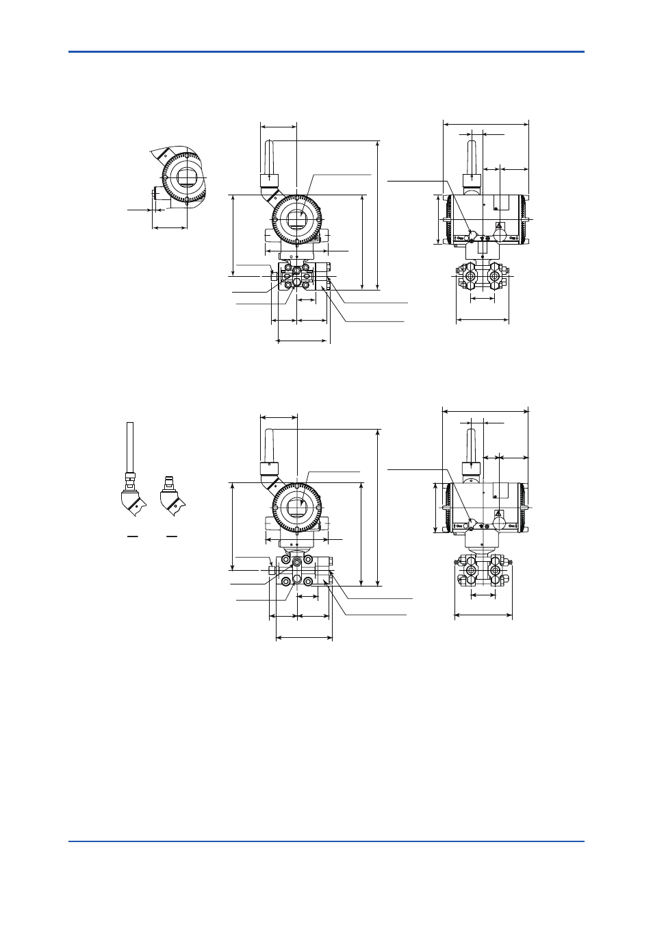
Universal flange type (Installation code U and Amplifier housing code 7)
(except for Measurement span code F)
82
*4
(3.23)
181 (7.13)
41
(1.61)
21
1 (8.31)
331
*2
(13.03)
140
(5.51)
67
(2.64)
115
(4.53)
58
(2.28)
Integral indicator
Process connection
Process connector
(Optional)
Drain plug
Drain plug
Vent plug
191 (7.52)
64
(2.52)
39
(1.54)
24
(0.94)
Ø
110 (4.33)
54
(2.13)
117
*1
(4.61)
High
pressure
side
Low
pressure
side
Universal flange type (Installation code U and Amplifier housing code 7)
(Measurement span code F)
*1: When option code K1, K2, K5, or K6 is selected, add 30 mm (1.18 inch) to the value in the figure..
*2: When amplifier housing code 8 is selected, the value is 390 mm (15.35 inch). When amplifier housing code 9 is
selected, the value is 270 mm (10.63 inch). In both cases, the figures are shown as A or B accordingly.
*3: When amplifier housing code 8 is selected, the value is 409 mm (16.10 inch). When amplifier housing code 9
is selected, the value is 289 mm (11.38 inch). In both cases, the figures are shown as A or B accordingly.
*4: When amplifier housing code 8 or 9 is selected, subtract 1 mm (0.04 inch) from the value.
82
*4
(3.23)
196 (7.72)
46
(1.81)
230 (9.06)
350
*3
(13.78)
140
(5.51)
72
(2.83)
125
(4.92)
63
(2.48)
Integral indicator
Process connection
Process connector
(Optional)
191 (7.52)
64
(2.52)
36
(1.42)
27
(1.06)
Ø
110 (4.33)
54
(2.13)
128
*1
(5.04)
High
pressure
side
Low
pressure
side
Zero adjustment
Drain plug
Drain plug
Vent plug
Zero adjustment
Unit: mm (approx. inch)
F05-01.ai
A
B
For electrical
connection code
5, 9, A, and D
6
(0.24)
76
(2.99)