General specifications – Yokogawa EJX430B User Manual
Page 103
<11. General Specifications>
11-12
IM 01C27B01-01EN
230 (9.06)
319
*8
(12.56)
105 (4.13)
257
*8
(10.12)
72 (2.83)
46
(1.81)
102 (4.02)
52
(2.05)
140 (5.51)
176
*6
(6.93)
234 (9.21)
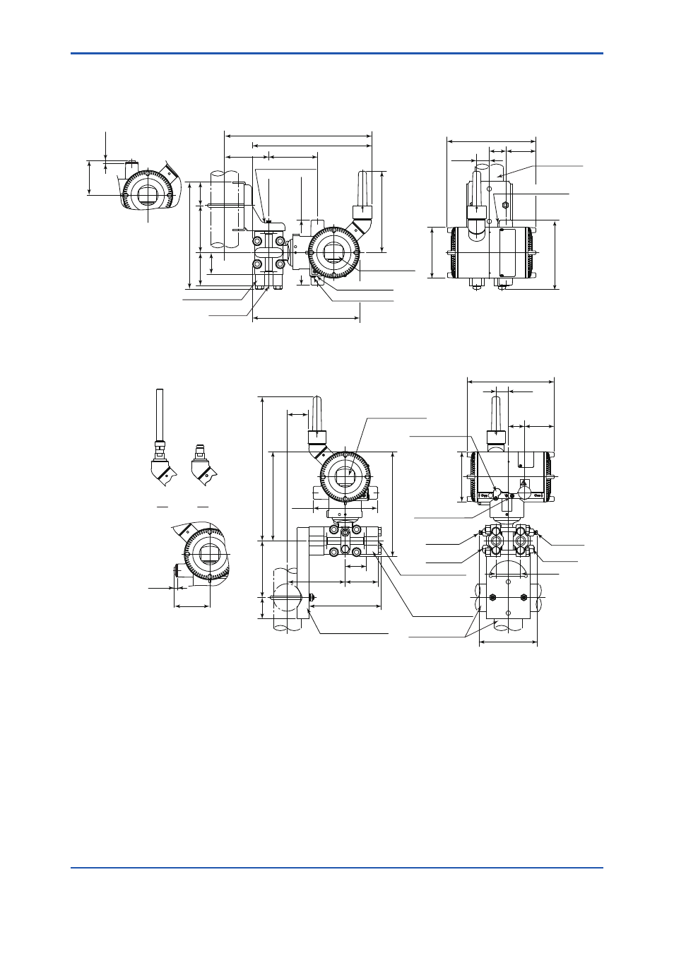
Vertical impulse piping type (Installation code 7 and Amplifier housing code 7)
Horizontal impulse piping type (Installation code 9 and Amplifier housing code 7)
*1
97 (3.82)
64
(2.52)
148 (5.83)
*2
191 (7.52)
36
*4
(1.42)
27
*5
(1.06)
64
(2.52)
191 (7.52)
36
*4
(1.42)
27
*5
(1.06)
Ø
110 (4.33)
2-inch pipe
(O. D. 60 mm)
Vent/Drain plugs
Process connector
(Optional)
Process
Connection
Integral indicator
Mounting bracket
(L-type, optional)
46
(1.81)
128
*3
(5.04)
47
(1.85)
Process connection
Process connector
(Optional)
Mounting bracket
(Flat-type, optional)
Integral indicator
45
*9
(1.77)
124 (4.88)
196 (7.72)
316
*7
(12.44)
230 (9.06)
140
(5.51)
72
(2.83)
127
(5.00)
158
(6.22)
Ø
110 (4.33)
Drain plug
Vent plug
Ground terminal
Zero adjustment
High
pressure
side
Low
pressure
side
High
pressure
side
Low
pressure
side
Vent plug
Drain plug
2-inch pipe
(O. D. 60 mm)
54
(2.13)
Ground terminal
Zero adjustment
Wetted parts material code H, M, T, A, B, and D or Measurement span code F
Wetted parts material code H, M, T, A, B, and D or Measurement span code F
Unit: mm (approx. inch)
F04.ai
A
B
*1: When installation code 8 is selected, high and low pressure side on above figure are reversed.
(i.e. High pressure side is on the right side.)
*2: When option code K1, K2, K5, or K6 is selected, add 15 mm (0.59 inch) to the value in the figure.
*3: When option code K1, K2, K5, or K6 is selected, add 30 mm (1.18 inch) to the value in the figure.
*4: 42 mm (1.65 inch) for right side high pressure.
*5: 21 mm (0.83 inch) for right side high pressure.
*6: When amplifier housing code 8 is selected, the value is 234 mm (9.21 inch). When amplifier housing code 9 is
selected, the value is 114 mm (4.49 inch). In both cases, the figures are shown as A or B accordingly.
*7: When amplifier housing code 8 is selected, the value is 374 mm (14.72 inch). When amplifier housing code 9
is selected, the value is 254 mm (10.00 inch). In both cases, the figures are shown as A or B accordingly.
*8: When amplifier housing code 8 or 9 is selected, subtract 1 mm (0.04 inch) from the value.
*9: When amplifier housing code 8 or 9 is selected, add 1 mm (0.04 inch) to the value.
For electrical
connection code
5, 9, A, and D
6
(0.24)
76
(2.99)
For electrical
connection code
5, 9, A, and D
6
(0.24)
76
(2.99)