6 changing the direction of integral indicator, 7 changing the direction of the antenna, Changing the direction of integral indicator -5 – Yokogawa EJX430B User Manual
Page 24: Changing the direction of the antenna -5, Warning
<4. Installation>
4-5
IM 01C27B01-01EN
F0407.ai
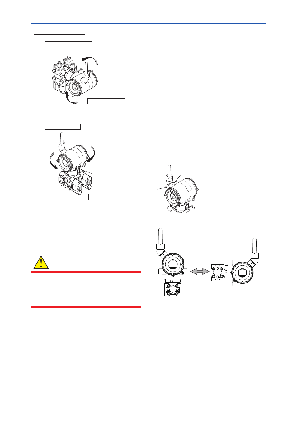
Vertical impulse piping type
Horizontal impulse piping type
Pressure-detector section
Transmitter section
Rotate 0 to ±180°
segments
Rotate 0 to ±180°
segments
Transmitter section
Pressure-detector section
Zero-adjustment screw
Figure 4.7
Rotating Transmitter Section (Left Side
High Pressure Type)
4.6 Changing the Direction of
Integral Indicator
WARNING
Intrinsic safe type transmitters must be, as a
rule, remove a battery pack in non-hazardous
area before open/close the Amplifier Cover or
disassembling and reassembling the Integral
Indicator.
An integral indicator can be rotated in four positions
at 90°. Follow the instructions in section 9.4.1 for
removing and attaching the integral indicator.
4.7 Changing the direction of
the antenna
Adjust the direction of the antenna to be in the
upright position. Figure4.8 shows factory setup
antenna position. If the transmitter is installed to
vertical impulse piping, follow the procedure below
and change the antenna position.
1) Loosen the two mounting screws at the bottom
of the antenna by using a 2.5 mm Allen wrench
(see Figure 4.8).
The screws might come off and be lost if
loosened too much; loosen the screws by about
three rotations.
2) Press forward and down 90 degrees by rotating
the axis at the bottom of the antenna.
3) Tighten the two screws to a torque of 1.5 N·m
by using a torque wrench. When doing this, be
careful not leave a gap between the antenna
and housing.
F0408.ai
Figure 4.8
Mounting Screw Position
F0409.ai
Figure 4.9
Adjusting Antenna Position