Output 1 & 2 wiring, Output 2 wiring – Watlow Series 945, 1/4 DIN Microprocessor-BasedAuto-tuning Control User Manual
Page 8
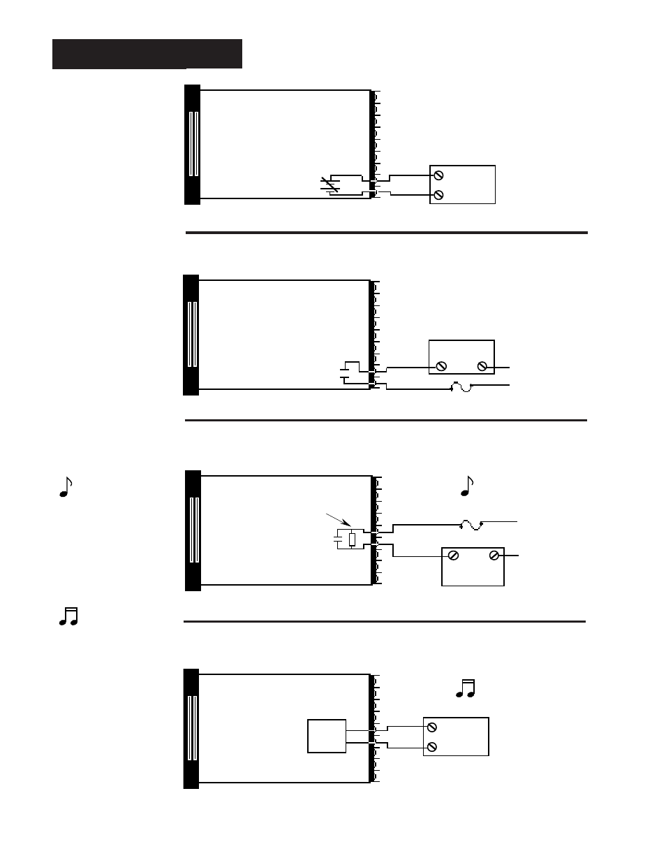
Install and Wire, Chapter 2
8
WATLOW Series 945 User's Manual
Output 1 & 2 Wiring
Output 1 - Process, 0 - 5VDC
N.O.
COM.
External
Load
Fuse
L1
L2
18
17
Solid State Relay, Form A, 0.5 Amp
Off state impedance: 31M
Ω
max.
945A - _
H
_ _ - _ 000
945A - _
K
_ _ - _ 000
Output 2 - Solid State Relay With Contact Suppression
Output 1 - Solid State Relay Without Contact Suppression
Figure 16 -
Solid State Relay
Without Contact
Suppression
Figure 15 -
Process, 0 - 5VDC
945A - _ _
B
_ - _ 000
Figure 17 -
Solid State Relay
With Contact
Suppression
NOTE:
This output is supplied
with an arc suppression
snubber across the
output terminals. High
impedance loads may
remain energized even
though the output device
is turned OFF.
18
17
External
Load
-
+
+
-
Load impedance: 10K
Ω
min.
COM.
N.O.
External
Load
Fuse
L1
L2
15
14
Off state impedance: 20K
Ω
max.
Suppression
15
14
Switched DC, Open Collector,
Non-Isolated
Logic
Switch
External
Load
-
+
Load impedance: 10K
Ω
min.
945A - _ _
C
_ - _ 000
Output 2 - Switched DC Output (Open Collector)
Figure 18 -
Switched DC Output
(Open Collector)
NOTE:
Minimum load resis-
tance is 500
Ω
. Available
current is 22mA
maximum. Typical
voltage drop across a
1K
Ω
load is 12 to 19
volts.