Chapter 2, Installation, How to install and wire the series 945 – Watlow Series 945, 1/4 DIN Microprocessor-BasedAuto-tuning Control User Manual
Page 4: Installation procedure, Dimensional information, Chapter 2 how to install and wire the series 945
Install and Wire, Chapter 2
4
WATLOW Series 945 User's Manual
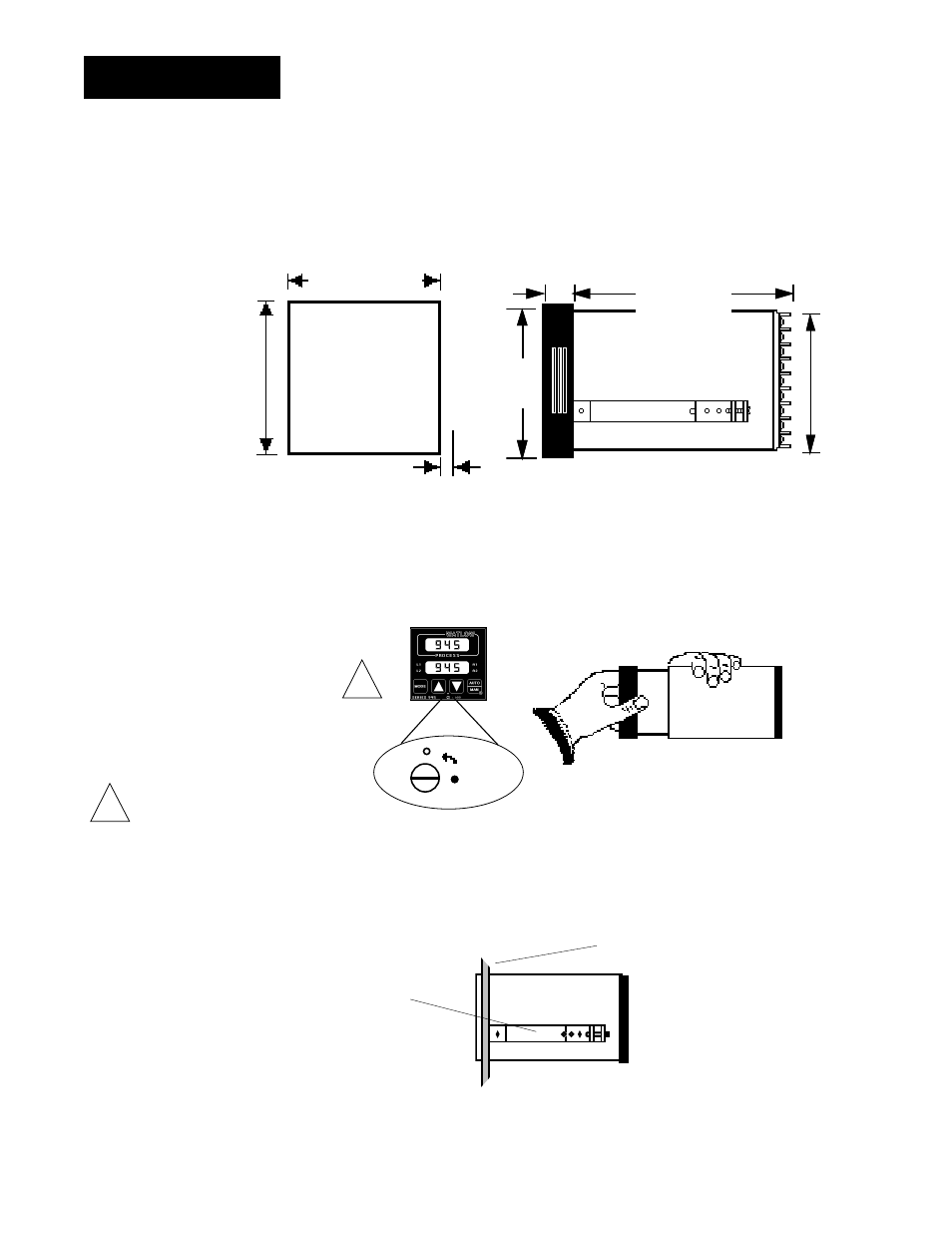
1. Make a panel cutout per the dimensions given below. Your panel thickness can
be from 0.06" to 0.25" (1.52 to 6.35 mm).
2. Remove the 945 from its case by turning the front panel screw 90
° counterclock-
wise (CCW). Grip the bezel firmly and pull the control out of the case.
3. Place the case in the cutout you just made. Attach the two mounting brackets,
shipped with your unit, either to the top and bottom, or to both sides of the unit.
Tighten the brackets securely against your panel.
4. Insert the control chassis into its case and press the bezel to seat it. Turn the
front panel screw 90
° clockwise (CW) to lock the control in place.
Installation
Figure 2 -
Series 945
Panel Cutout and
Unit Dimensions
CAUTION:
The front panel
screw turns 90
°
only. Do not apply
excessive force or
turn the screw more
than 90
°
.
!
Chapter 2
How to Install and Wire the Series 945
LOCK
!
3.62" to 3.65" sq.
(92 to 92.25 mm)
Panel
Cutout
3.63" X 3.63"
(92.08 X 92.08 mm)
3.8" sq.
(97 mm)
3.6"
± 0.015"
(90 mm
± 0.381)
0.92"
(23 mm)
6.0"
(152 mm)
Figure 3 -
How to Open the
Series 945.
Bezel
0.17" sq.
Dimension
(4 mm)
Mounting Bracket
Panel
Figure 4 -
Mounting the
Series 945 Case.