Chapter 2, Install and wire, Installation procedure – Watlow Series 94 User Manual
Page 7: Install and wire the series 94
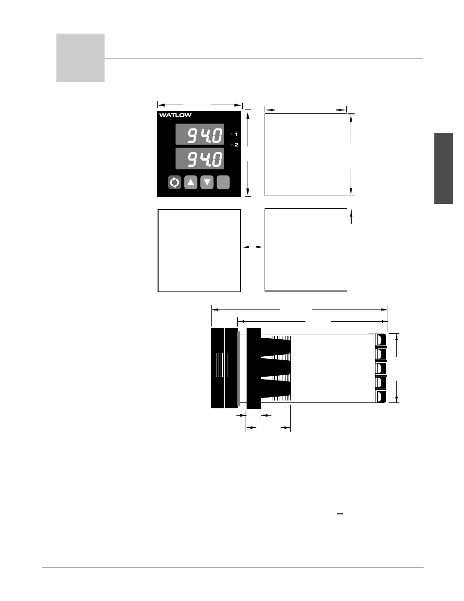
Panel Cutout
Your Panel
Thickness
0.06" to 0.38"
(1.5 to 9.7 mm)
1.77" to 1.79"
(44.96mm to 45.47mm)
1.77" to 1.79"
(44.96mm
to 45.47mm)
0.38"
(9.65mm)
Minimum
0.85"
(20mm)
LIMIT 94
2.1"
(53 mm)
2.1"
(53mm)
RESET
W a t l o w S e r i e s 9 4
I n s t a l l a n d W i r e
■
2 . 1
Install and Wire
Figure 2.1a -
Series 94 Multiple
Panel Cutout
Dimensions.
Installation Procedure
Bold print denotes requirement for NEMA 4X seal. Follow this proce-
dure to mount the Watlow Series 94 temperature control:
1.
Make a panel cutout using the dimensions in Figure 1a.
2.
If your controller model number begins with 94B, make sure the
rounded side of the external case gasket is facing the panel sur-
face. Check to see that the gasket is not twisted, and is seated within the
case bezel flush with the panel. Place the case in the cutout. Make sure
the gasket is between the panel cutout and the case bezel.
NOTE:
Measurements
between panel
cutouts are the mini-
mum recommended.
Figure 2.1b-
Series 94
Dimensions.
0.40"
(10mm)
1.21"
(31mm)
4.1"
(104mm)
4.7"
(119mm)
1.76"
(45mm)
2
Install and Wire the Series 94
NOTE:
For rapid mounting,
use Greenlee 1/16
DIN punch, die, draw
stud, part number
60287.