System wiring example, Figure 12 - series 92 system wiring examples – Watlow Series 92 User Manual
Page 8
8
WATLOW Series 92 User's Manual
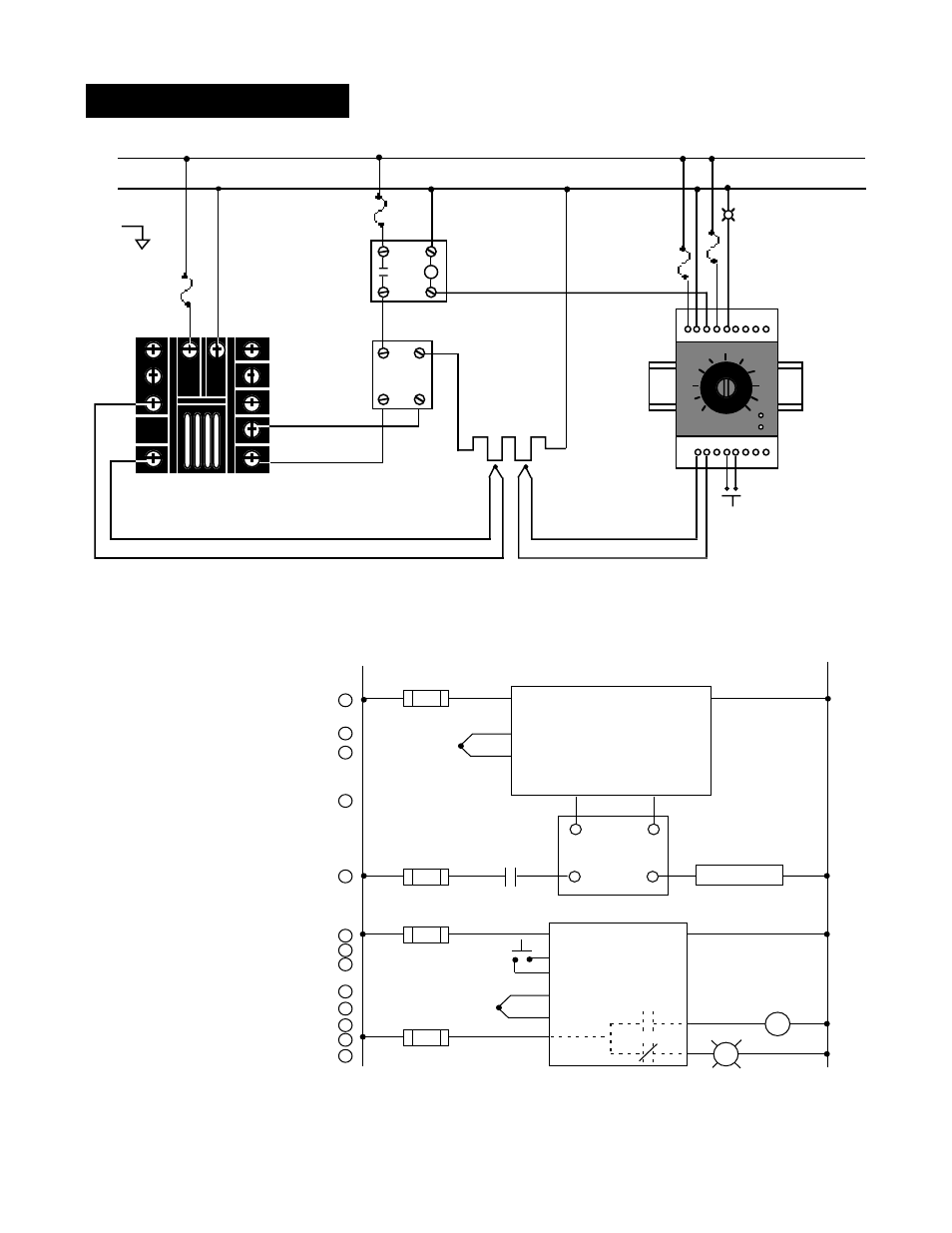
Figure 12 - Series 92 System Wiring Examples
965A-3CA0-0000
Rear View
(+)
5
3
12
11
9
10
(-)
L1
L2
-
120 VAC
Fuse
92A3-1DJ1-0000
Limit Control
Heater
Process Sensor
Limit Sensor
Optional
Normally Open
Momentary Switch
Red
High Limit
Mechanical
Contactor
Earth Ground
+
DC Input
SSR
SSR-240-10G-DC1
In
Out
1
2
4
3
13
14
10
+
11
-
High temp. light
Coil
System Wiring Example
1
120VAC
L1
L2
2
3
5
4
5
1
2
1
2
(+)
(-)
3
11
18
12
13
14
15
2
1CR
16
Hi Temp. Light
1
2
3
4
8
9
10
11
12
R
SSR-240-10G-DC1
DC Input Solid State Relay
17
1
8
Heater
Out
24-240VAC
(+)
(-)
3-32VDC
In
1 CR-1
9
10
2
9
10
6
7
11
12
5
6
7
Limit Control
Series 965
965A-3CA0-0000
Temperature control
Series 92
92A3-1DJ1-0000
13
4
3
5
11
1
2
13
14
10
(+)
(-)
з
з
з
з
з
WARNING: The
Series 92 Temperature
Limit Switch should be
mounted in an incon-
spicuous location to
discourage unautho-
rized changes to the
set point. Only ap-
proved and appropriate
personnel should have
the authority to change
the set point on the
limit switch. Failure to
comply with these
recommendations
could result in damage
to equipment and
property, and injury to
personnel.