Input wiring – Watlow Series 92 User Manual
Page 6
6
WATLOW Series 92 User's Manual
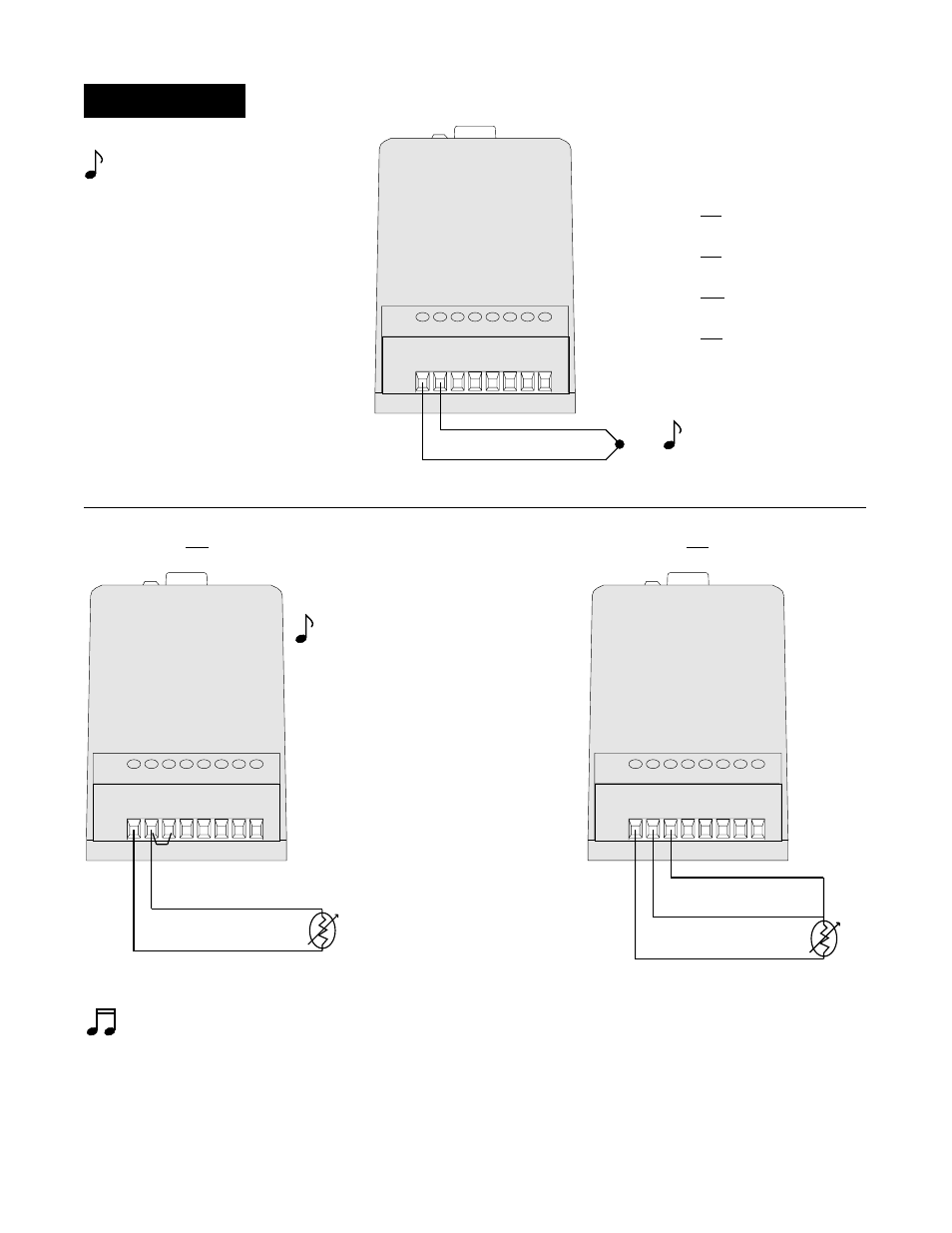
Input Wiring
NOTE:
When an external device with a non-
isolated circuit common is connected
to the DC (open collector) output, you
must use an isolated or ungrounded
thermocouple.
k
NOTE:
Jumper Terminals 11 and 12
for a 2 wire RTD.
2 Wire RTD
3 Wire RTD
NOTE:
Long lead lengths create electrical resistance. There will be approximately +2
°
C input error for every 1
Ω
of lead
length resistance, when using a two wire RTD. That resistance, when added to the resistance of the RTD element,
can result in erroneous input to the instrument. To overcome this problem, use a three wire RTD sensor, which
compensates for lead length resistance. When extension wire is used for a three wire RTD, all three extension wires
must have the same electrical resistance. (i.e. same gauge, copper stranded.)
Figure 7 - RTD Wiring
Figure 6 - Thermocouple Wiring
k
10 11 12 13 14 15 16 17
+
-
Red
92XX - XX
P1
- X0XX
92XX - XX
P1
- X0XX
92XX - XX
J1
- X0XX
92XX - XX
J2
- X0XX
92XX - XX
K1
- X0XX
92XX - XX
T1
- X0XX
10 11 12 13 14 15 16 17
S1
S2
10 11 12 13 14 15 16 17
S1
S2
S3