Installation, Removing mounting – Watlow Series 92 User Manual
Page 4
4
WATLOW Series 92 User's Manual
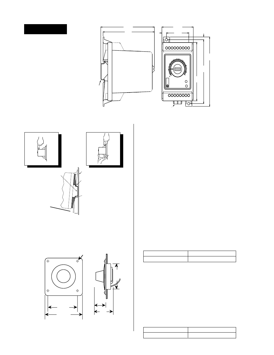
Installation
Removing
Mounting
Panel
DIN Rail
Upper
Mounting
Clip
Lower
Mounting
Clip
Snap Action
Release
Lever
DIN-Rail Mounting the Series 92
1. Place the Series 92 upper mounting clip on the top edge
of the DIN rail. See Figure 2.
2. Press down firmly on the top front edge of the Series 92,
see Figure 2
Mounting for location. The control "snaps"
securely onto the rail. If the control does not snap on,
check to see if the DIN rail is bent. The DIN rail specifica-
tion is DIN EN 50022, 35 mm X 7.5 mm. Minimum
clipping distance is 1.37" (34.8mm), the maximum is
1.39" (35.3mm).
Removing the Series 92 from the DIN-Rail
1. Place your fingers on the release lever located at the
base of the Series 92. See Figure 2
Removing.
2. While gently pressing on the top of the case, above
Terminals 1 - 9 (see Figure 2 inset), pull forward on the
release lever.
Mounting the Series 92
1. Using the control as a location template, mark both
mounting holes.
2. Drill two 0.19" (5 mm) diameter holes in desired panel
location See Figure 1.
Tap drill size
for
Screw/thread size
#29 - 0.136 dia.
#8-32
3.3 mm
M4 x 0.7
Installing the Remote Setpot Assembly
1. Drill a 2.25" (57 mm) diameter hole (or use a 2.25", or
2.375" punch) at desired remote setpot assembly loca-
tion. See Figure 3.
2. Using the dial scale as a location template, center and
mark all four mounting holes on the dial scale with a
center punch.
3. For a bolted dial scale assembly, drill four 0.125" (3 mm)
diameter clearance holes. If you are using a screw
assembly, use a tap drill.
Tap drill size
for
Screw/thread size
#43 - 0.089 dia.
#4-40
#42 - 0.093 dia.
#4-48
Figure 1 - Series 92 Dimensions
1 2 3 4 5 6 7 8 9
10 11 12 13 14 15 16 17
TYPE J T/C
SERIES 92
LOAD
BAND
0
100
300
700
800
1000
1100
1300
100
200
300
500
600
700
500
750
F
C
4.45"
(113 mm)
2.28"
(58 mm)
3.72"
(95 mm)
3.89"
(99 mm)
1.62"
(41 mm)
4.10"
(104 mm)
3.75"
(95 mm)
0.33"
(8 mm)
0.18"
(5 mm)
Release Lever
35mm X 7.5mm
Rail is not included
in the assembly
Figure 2 - Series 92 Side View Mounting
Figure 3 - Setpot Dimensions
2.69" sq.
(68 mm)
3.00" sq.
(76 mm)
0.11" Dia.
(3 mm)
4 mounting holes
0.75"
(19.05mm)
(36 mm)
1.4"
2.25"
(57 mm)