Setup procedure for open-heater alarm, Phase, 2-leg open heater alarm, Model dc2 _ - _ _ s _ - h _ _ _ ) – Watlow DIN-A-MITE Style C User Manual
Page 12
12
WATLOW DIN-A-MITE Style C User's Manual
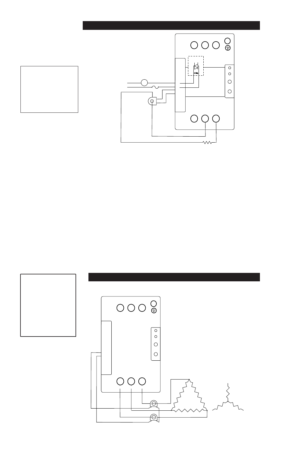
Alarm Relay
or Indicator
V~
120 or 240V~
@ 300mA maximum
energizes on alarm
1A
7
8
9
10
11
12
13
14
15
16
17
18
19
20
1 2 3
4
Signal
Alarm
Gain
Bias
Open
Heater
Limit
+
-
+
-
+
-
ALM
ALM
CT1
CT1
CT2
CT2
CT3
CT3
Adjustment
Potentiometers
Triac
Zone
1
Zone
2
Zone
3
ALM = Alarm
CT = Current Transformer
Current
Transformer
(CT)
Heater
Load Wire
5
6
Single-phase Alarm
Non-latching Alarm Option
DC _ _ - _ _ _ _ - [H, S] _ _ _
NOTE:If you plan to wire
multiple DIN-A-MITE
alarm outputs, you need
to include an
intermediate relay for
each DIN-A-MITE used.
The Watlow DIN-A-MITE alarm option provides
a common alarm output for open-heater or
shorted SCR conditions. This is a non-latching
alarm.
• A shorted SCR alarm is detected when there is
no command signal and a load current is
detected. The alarm output is then energized.
• An open-heater or partial open-heater state is
detected when a command signal is present and
a reduced or no output current is detected. The
alarm output is then energized.
Setup Procedure for Open-Heater Alarm
(For Input Control Signal type S option only)
1. With the temperature control wired to the
DIN-A-MITE SCR power control, set the
temperature control output to “full on” (20mA
for 4 to 20mA output, or 5V for 0 to 5V output).
2. Adjust the open heater alarm adjustment
potentiometer until the alarm indicator light on
the front panel is full on, with no intermittent
cycling.
3. Slowly adjust the potentiometer until the
open heater indicator light just turns full off,
with no intermittent cycling.
If you are getting false alarms, the adjustment is
probably set too sensitive and should be re-
adjusted towards the off condition of the open-
heater indicator light.
No setup procedure required for shorted SCR alarm.
Load Current -
Single phase load
wire passes through
one CT. Number of
passes through CT:
5 to 9A
2
10 to 65A
1
T1
T2
T3
7
8
9
10
11
12
13
14
15
16
17
18
19
20
Gain
Bias
Open
Heater
Limit
+
-
+
-
+
-
ALM
ALM
CT1
CT1
CT2
CT2
CT3
CT3
Adjustment
Potentiometers
Signal
Alarm
4 5 6
1 2 3
Zone
1
Zone
2
Zone
3
ALM = Alarm
CT = Current Transformer
Heater
Current Transformers
white
black
3-phase, 2-leg Open Heater Alarm
NOTE:
Load wires must pass
through each current
transformer in the same
direction.
(Model DC2 _ - _ _ S _ - H _ _ _ )
з
У
1
У
3
з
У
1
У
3
Load Current -
3-phase 2-leg load wire
passes through 2 CTs.
Number of passes
through each:
5 to 6A
7
7 to 9A
6
10 to 14A
4
15 to 19A
3
20 to 33A
2
34A and up
1