High gain t/c, High gain thermocouple input, High gain thermocouple input procedure – Watlow Calibrating Watlow Series 988 Family Process Controls User Manual
Page 9
WATLOW Series 988 Calibration Manual
9
High Gain T/C
High Gain Thermocouple Input Procedure
Type R, S and B only
Equipment Required
•
Type J reference compensator with reference junction at 32
°
F/0
°
C, or
Type J thermocouple calibrator set at 32
°
F/0
°
C
•
Precision millivolt source, 0 - 50mV minimum range, 0.01mV resolution
Setup and Calibration
1. Connect the AC voltage L1, L2 and ground to the proper terminals on the
Series 988. See Chapter 2 in the user's manual.
2. For Input #1 calibration: Connect the millivolt source to terminal #9 (+) and
terminal #10 (-) on the 988 terminal strip. Use 20 to 24 gauge copper wire. If
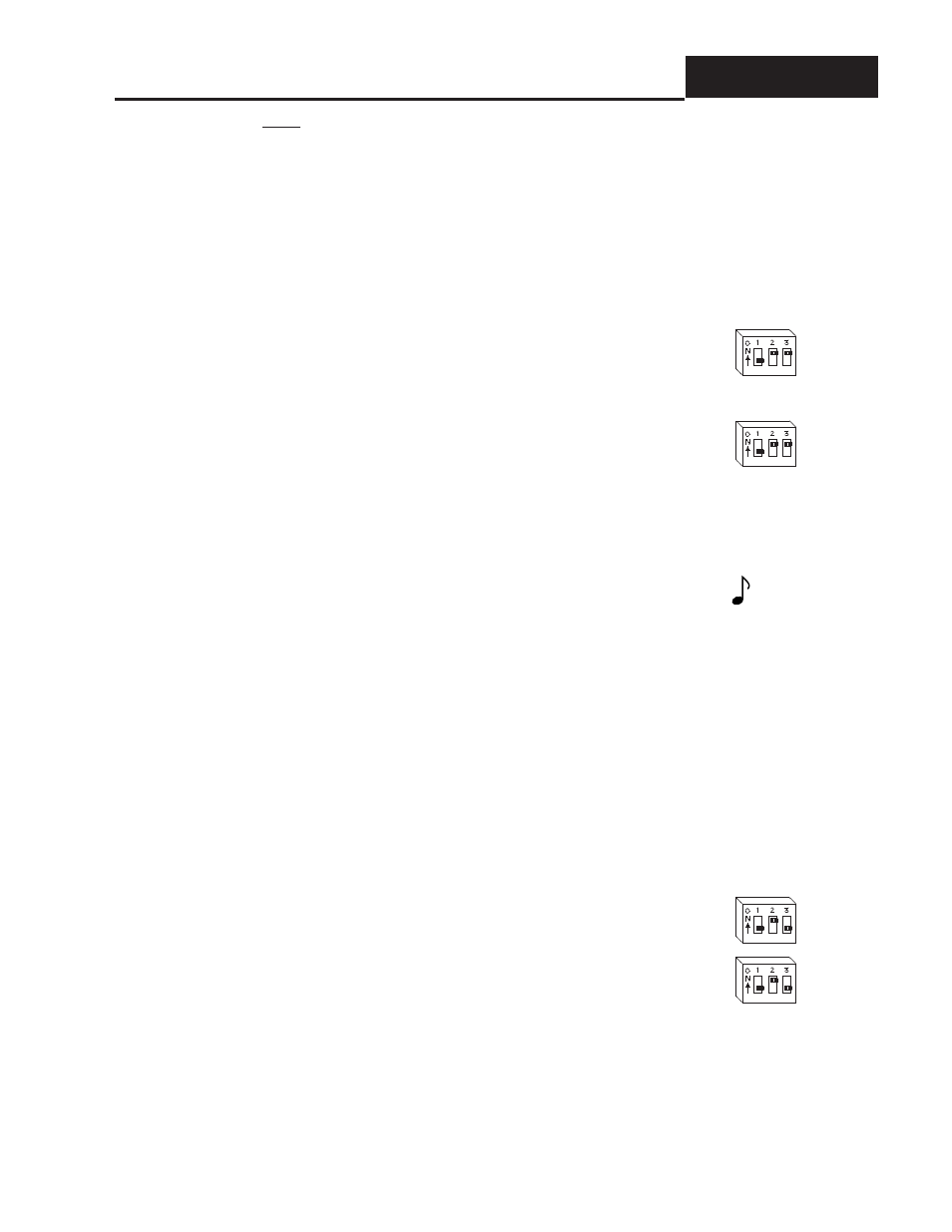
you have model number 98_ _ - 2 _ _ _ - _ _ _ _, remove the control from the
case and set the Input 1 DIP switches to:
1 OFF
2 ON
3 ON
For Input #2 calibration: Connect the millivolt source to terminal #19 (+) and
terminal #20 (-) on the 988 terminal strip. Use 20 to 24 gauge copper wire. If
you have model number 98_ _ - _2 _ _ - _ _ _ _, remove the control from the
case and set the Input 2 DIP switches to:
1 OFF
2 ON
3 ON
3. Apply power to the unit and let it warm up for 15 minutes. After warm up put
the unit in the CAL menu. See Page 6.
When performing calibration procedures, always do the Input 1 prompts
(beginning with an “A”) first, then continue on to the Input 2 prompts
(beginning with a “B”). See the Calibration menu on Page 6.
4. At the A 50 or B 50 prompt, enter 50.00mV from the millivolt source to the
Series 988. Allow at least 10 seconds to stabilize. Press the Up key to change
the upper display to YES. Press the Mode key.
5. At the A 00 or B 00 prompt, enter 0.00mV from the millivolt source to the
Series 988. Allow at least 10 seconds to stabilize. Press the Up key to change
the upper display to YES. Press the Mode key.
6. At the tc prompt, disconnect the millivolt source, and connect the reference
compensator or T/C calibrator to terminal #9 (+) and terminal #10 (-) on the 988
terminal strip. If using a compensator, turn on and short the input wires. If
using a J calibrator, set it to simulate 32
°
F/0
°
C. Allow 10 seconds for the con-
trol to stabilize. Press the Up key to change the upper display to YES. To con-
clude the T/C calibration, press the Display key.
7. For Input #1 calibration: Remove the control from the case and set the
Input #1 DIP switches to: 1 OFF
2 ON
3 OFF
8. For Input #2 calibration: Remove the control from the case and set the Input
#2 DIP switches to:
1 OFF
2 ON
3 OFF
9. At the A 0H or B 0H prompt, enter 0.00 mV from the millivolt source to the
Series 988. Allow at least 10 seconds to stabilize. Press the Up key to change
the upper display to YES. Press the Mode key.
10.At the A 20 or B 20 prompt, enter 20.00 mV from the millivolt source to the
Series 988. Allow at least 10 seconds to stabilize. Press the Up key to change
the upper display to YES. Press and hold the Mode key, while also pressing
the Up key until the lower display reads tc.
NOTE:
Any prompt begin-
ning with an “A”
applies to Input 1.
Those beginning
with a “B” apply to
Input 2.