Ma process input, Ma process input procedure – Watlow Calibrating Watlow Series 988 Family Process Controls User Manual
Page 11
WATLOW Series 988 Calibration Manual
11
mA Process Input
mA Process Input Procedure
0 to 20mA and 4 to 20mA units
Equipment Required
•
Precision current source, 0-20mA range with 0.01mA resolution
Setup and Calibration
1. Connect the AC voltage L1, L2 and ground to the proper terminals on the
Series 988. See Chapter 2 in the user's manual.
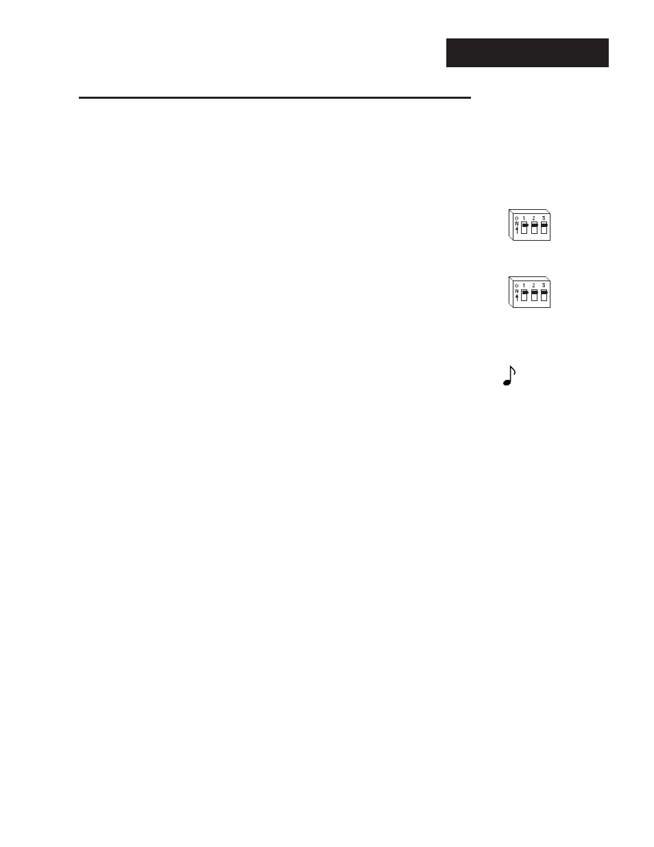
2. For Input #1 calibration: Connect the voltage source to terminal #8 (-) and
terminal #10 (+) on the 988 terminal strip. Use 20 to 24 gauge copper wire.
Remove the control from the case and set the Input 1 DIP switches to:
1 ON
2 ON
3 ON
For Input #2 calibration: Connect the voltage source to terminal #18 (-) and
terminal #20 (+) on the 988 terminal strip. Use 20 to 24 gauge copper wire.
Remove the control from the case and set the Input 2 DIP switches to:
1 ON
2 ON
3 ON
3. Apply power to the unit and let it warm up for 15 minutes. After warm up put
the unit in the CAL menu. See Page 6.
When performing calibration procedures, always do the Input 1 prompts
(beginning with an “A”) first, then continue on to the Input 2 prompts
(beginning with a “B”). See the Calibration menu on Page 6.
4. At the A20A or B20A prompt, enter 20.00mA from the current source to the
Series 988. Allow at least 10 seconds to stabilize. Press the Up key to change
the upper display to YES. Press the Mode key.
5. At the A 4A or B 4A prompt, enter 4.00mA from the current source to the
Series 988. Allow at least 10 seconds to stabilize. Press the Up key to change
the upper display to YES. Press the Mode key. To conclude the current
process calibration, press the Display key.
NOTE:
Any prompt begin-
ning with an “A”
applies to Input 1.
Those beginning
with a “B” apply to
Input 2.