1 system design, 1 ps3000-ba, 1 system design -2 – Proface APL3000B - Node Box PC User Manual
Page 15: 1 ps3000-ba -2, System design, 2 1.1 system design
PS-3000B Series Hardware Manual
1-2
1.1
System Design
1.1.1
PS3000-BA
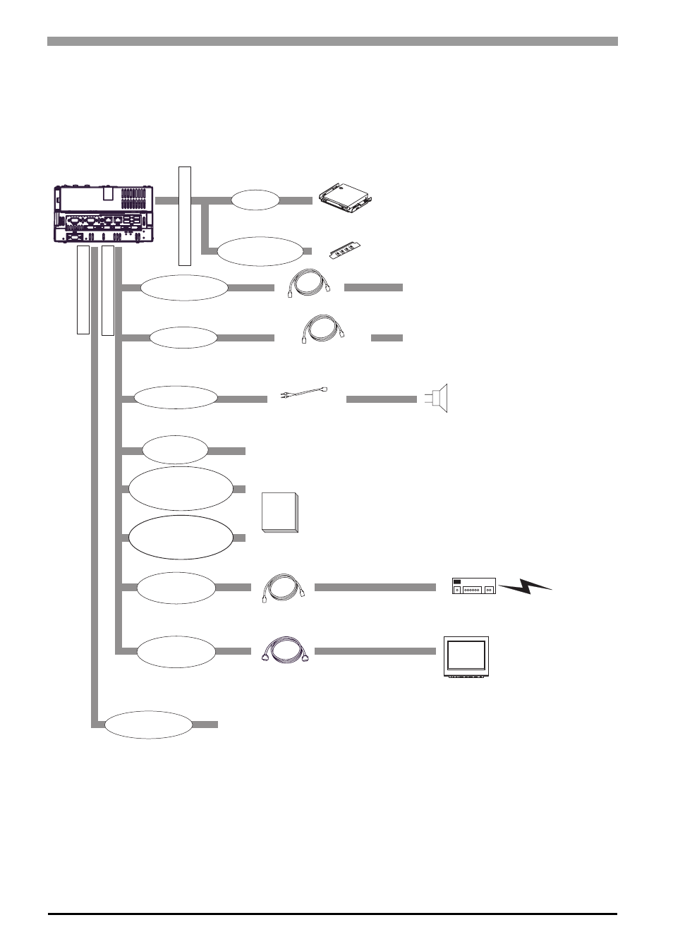
The following diagram illustrates the standard range of items that can be connected to PS3000-BA units.
PS3000-BA
Inside of PS-B’
s T
o
p
Front of PS-B unit
Side of PS-B
unit
CF
IDE I/F
*1 Built-in accessory only
*2 Pro-face's optional devices and commercial products.
*3 When setting RS-232C mode for COM2.
*4 When setting RS-422 or RS-485 mode for COM2.
Please refer to 1.2 Accessories.
USB I/F
(4 ports)
Primary CF Card I/F
(TYPE ll, 1 port)
Secondary CF Card I/F
(TYPE ll, 1 port)
Speaker Out I/F
Hub
Speaker
Central Network Line
HDD Unit
*1 *2
Main Memory Module
*1 *2
CF Cards
*2
*2
Main Memory I/F
Peripherals
(commercial type)
Peripherals
(commercial type)
USB 2.0 Compatible Peripherals
(commercial type)
Pin-jack Cable
(commercial type)
LAN1:10BASE-T/100BASE-TX Cable (commercial type)
RS-232C Cable
COM1/COM2
*3
*4
COM2
RS-422 Cable
RS-485 Cable
Ethernet I/F
(2 ports)
Analog RGB I/F
Analog RGB Cable
(commercial type or optional devices )
RGB Monitor
(commercial type or Pro-face’s FP Series)
LAN2:10BASE-T/100BASE-TX/1000BASE-T Cable (commercial type)
Expansion unit I/F
PCI Board
(commercial type)