Spreader maintenance, Important, Caution – SaltDogg TGSUVPROA Salt Spreader User Manual
Page 4
Quality since 1946
4
9049 Tyler Blvd. • Mentor, Ohio 44060
Phone (440) 974-8888 • Fax (440) 974-0165
Toll-Free Fax 800-841-8003 • buyersproducts.com
3017110 Rev. A
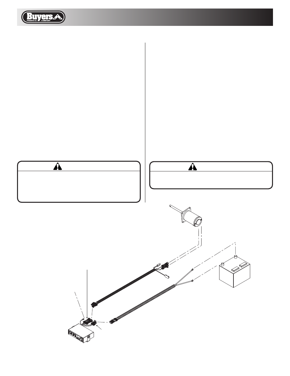
9. Connect the wire harness to the motor.
Thoroughly clean battery terminals. Make sure
battery terminals have no tarnish or corrosion.
DO NOT CONNECT WIRE HARNESS TO
DAMAGED OR CORRODED TERMINALS!
IT MAY RESULT IN OVERHEATING, LOST
POWER AND POTENTIAL CONTROLLER
DAMAGE!
10. Connect the power cable directly to the battery.
11. Insure all functions of the controller are
working properly.
12. Observe spinner direction of rotation. The
correct direction is counter clock wise when look-
ing inside hopper from the top. If direction is
clock wise reverse wires between Motor and Wire
Harness.
Spreader Maintenance
1. This spreader is designed to use loose free
floating materials such as #1 dry Rock Salt. Using
different grades and/or wet material will affect
spreader performance. Wet material can “bridge"
and stop floating onto spinner disk.
2. Make sure lid is installed and latches are
secured when spreader is in use.
3. Do not leave material in hopper between uses.
4. Do not drive with material in hopper.
5. Always clean/ wash hopper at the end of
the day.
6. Spray lubricant around motor shaft to prevent
water from penetrating into the motor.
7. Apply dielectric grease to all electrical
connectors between uses and for long term
storage.
IMPORTANT
IMPORTANT Make sure all wires securely attached to
vehicle or spreader’s frame. Use wire ties and/or wire
clamps to attach wires. All excess wires must be rolled
into bungles and attached to vehicle or spreader.
CAUTION
Do not attempt to tilt spreader with material in it and/
or while vehicle is moving.
BATTERY
MOTOR
PART #3014441
CONTROLLER
PART #3011864
POWER CABLE
PART #3008615
WIRE HARNESS
PART #3008620
FUSE CONNECTOR
CONNECTOR TO FUSE TERMINAL
OR IGNITION SWITCH
2-PIN CONNECTOR
4-PIN CONNECTOR
Fig. 5