Rf and dc measurement system configuration, Figure 1 system block diagram, Figure 1. system block diagram – Agilent Technologies 85225F User Manual
Page 19: And dc measurement system configuration
Introducing the Agilent 85225F Performance Modeling System
1
Installation and User’s Guide
19
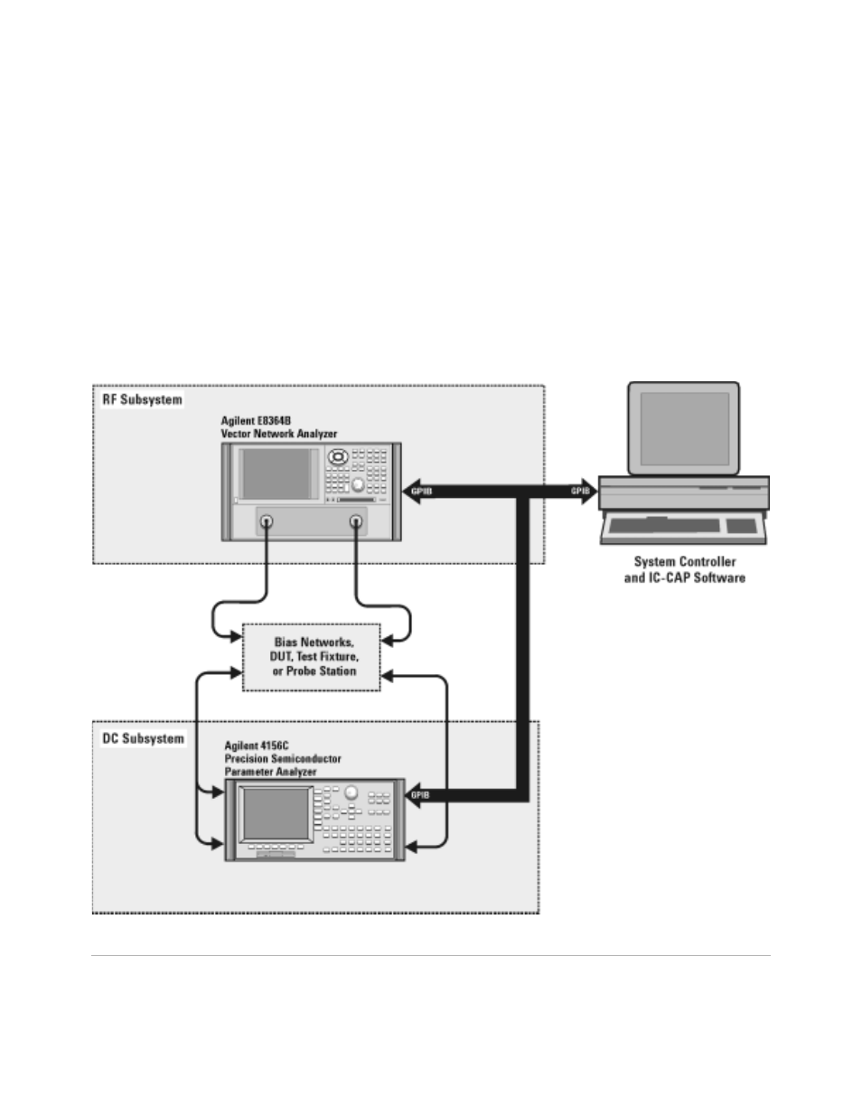
RF and DC Measurement System Configuration
In conjunction with a compatible controller running 85190- Series IC- CAP
software, the Agilent 85225F performance modeling system measures the
DC and RF performance of active and passive devices. The IC- CAP
software then extracts the device parameters and displays the results.
The Agilent 85225F performance modeling system is the integration of
rack- mounted RF and DC subsystems, bias networks, and a system
controller
*
.
* The system controller is not included and must be provided.
† This block diagram shows a system with an Agilent 4156C as the DC subsystem. Other instrumentation may
be used. See
Figure 1
System Block Diagram