Appendix d connector pinouts, Connector pinouts – ADTRAN 3000 User Manual
Page 129
61203153L2-20
Express 3000 User Manual
D-1
Appendix D
Connector Pinouts
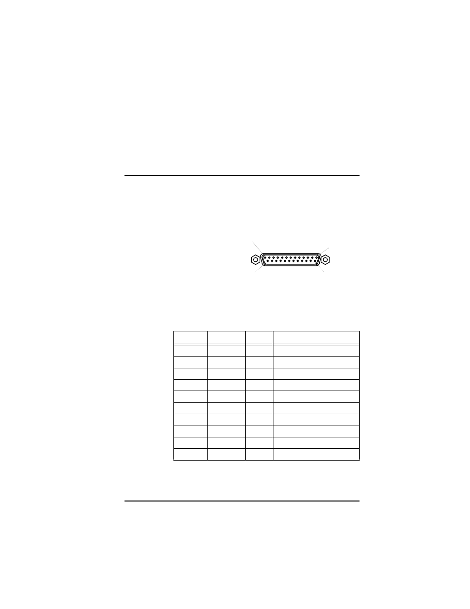
This appendix describes the various connector pinouts used with the
Express 3000. Figure D-1 shows the EIA-232 interface and Table D-1
shows the EIA-232 pinout.
Figure D-1. EIA-232 Interface
Table D-1.
EIA-232 Interface Pinout
Pin
Name
I/O
Description
1
Shield
I/O
Shield for Cable
2
TD
I
Transmitted Data
3
RD
O
Received Data
4
RTS
I
Request to Send
5
CTS
O
Clear to Send
6
DSR
O
Data Set Ready
7
SG
I/O
Signal Ground
8
CD
O
Carrier Detect
20
DTR
I
Data Terminal Ready
22
I
RI
I = Input O = Output
PIN 13
PIN 1
PIN 25
PIN 14
FEMALE