Gas supply connections – Lincoln Electric 718114 Spirit II 150 User Manual
Page 39
Spirit II User’s Manual
Section 3: Installation
This information is subject to the controls of the Export Administration Regulations [EAR]. This information shall not be provided to
non-U.S. persons or transferred by any means to any location outside the United States contrary to the requirements of the EAR.
3-17
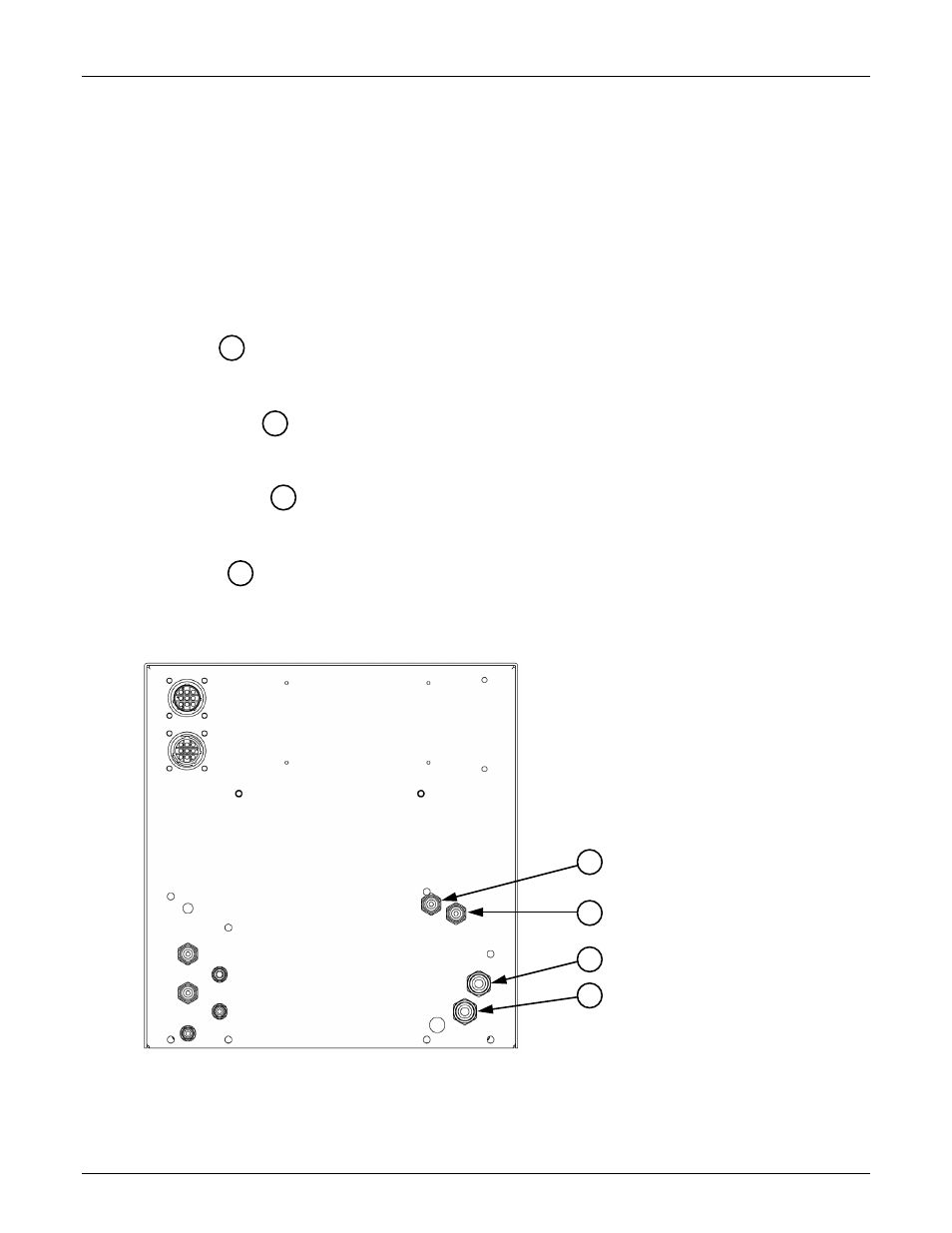
Gas Supply Connections
Perform the following steps to connect the gas supply lines to the MGC. See Section 2
for gas supply requirements. Mating hose barbs and connectors are supplied with the
system and are sized for 3/8 inch inside diameter hose.
Do not change the inlet gas
supply fittings to quick-connect fittings. Using quick-connect fittings to connect
and disconnect pressurized hoses may cause damage to the system.
Note: When making hose connections, only tighten the brass fittings enough to
make gas seals. The fittings are subject to damage if over tightened.
Air Inlet (ISO 3821 hose color - black)
•
Air must be supplied to the unit at all times, regardless of the cutting current or
material type.
Oxygen Inlet (ISO 3821 hose color - blue)
•
Oxygen must be supplied to the unit at all times, unless stainless steel is being cut
with H17 plasma.
Nitrogen Inlet (ISO 3821 hose color - black)
•
Nitrogen must be supplied to the unit at all times, regardless of the cutting current or
material type.
H17 Inlet (ISO 3821 hose color - red)
•
H17 must be supplied to the unit when stainless steel is being cut with H17 as the
plasma gas. See cutting charts in Section 5 for more information.
32
34
31
33
31
32
33
34