Installation, Warning – Lincoln Electric IM10085 ACTIV8 User Manual
Page 14
A-5
INSTALLATION
ACTIV8™
A-5
PRESSURE ARM ADJUSTMENT
ELECTRIC SHOCK can kill.
• Turn the input power OFF at the weld-
ing power source before installation or
changing drive rolls and/or guides.
• Do not touch electrically live parts.
• When inching with the gun trigger, electrode
and drive mechanism are "hot" to work and
ground and could remain energized several sec-
onds after the gun trigger is released.
• Do not operate with covers, panels or guards
removed or open.
• Only qualified personnel should perform mainte-
nance work.
------------------------------------------------------------------------
The pressure arm controls the amount of force the
drive rolls exert on the wire. Proper adjustment of the
pressure arm gives the best welding performance.
Many welding problems can be attributed to setting
the pressure arm too high and causing wire deforma-
tion. Set the pressure arm to minimum amount that
provides reliable feeding.
Set the pressure arm as follows:
Cored wires
between 1 and 3
Steel, Stainless wires
between 3 and 5
WARNING
LOADING SPOOLS OF WIRE
• Keep hands, hair, clothing and tools
away from rotating equipment.
• Do not wear gloves when threading wire
or changing wire spool.
• Only qualified personnel should install, use or
service this equipment.
------------------------------------------------------------------------
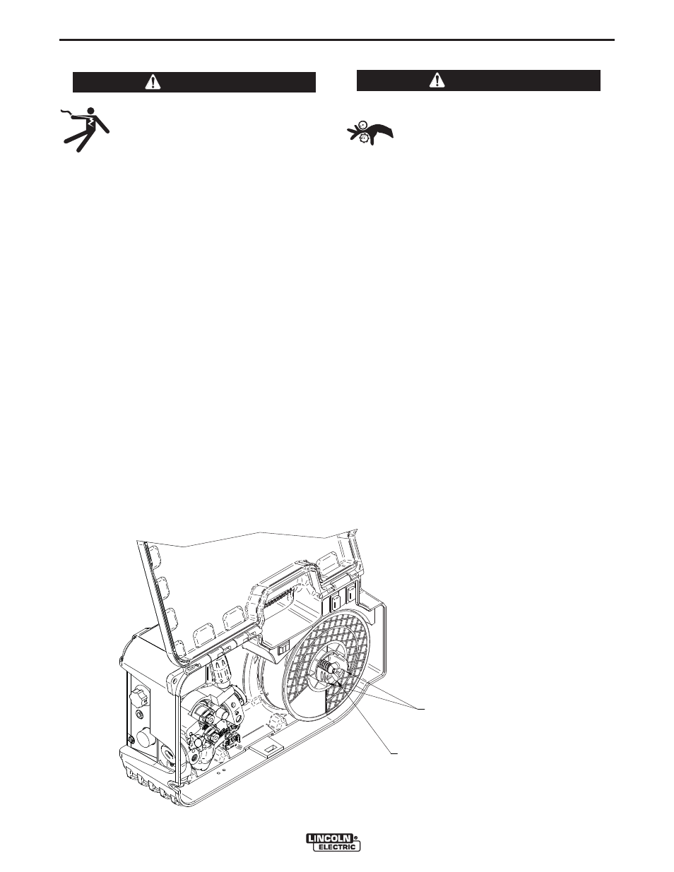
SPOOL RETAINER
When loading and removing the 8” spools make sure
that the wing nut (inside the wire reel spindle hub) is
turned 90° from the wire reel spindle locking tabs. If
the wing nut is positioned in line with the locking tabs,
the tabs cannot be depressed to load or unload the
wire spool. (See Fig A.2)
The wire spool must be pushed all the way on the
spindle so that both the spindleʼs tabs will hold it in
place. The wire spool will rotate counter clockwise
when wire is de-reeled.
SPOOL BRAKE
Adjust the spool brake with wire spool installed, to
provide enough friction to stop wire overrun. To
adjust the brake turn the wing nut clockwise to
increase the brake, and counterclockwise to loosen
the brake.
Excessive brake force may cause motor thermal over-
loads or welding problems.
WARNING
WING NUT
WIRE REEL SPINDLE
MOUNTING TABS
FIGURE A.2