12 at/atx mode selection, At/atx, Election – IEI Integration AFL-19i-HM55 v1.01 User Manual
Page 61: Figure 3-28: vga connector
AFL-HM55 Series Panel PC
Page 49
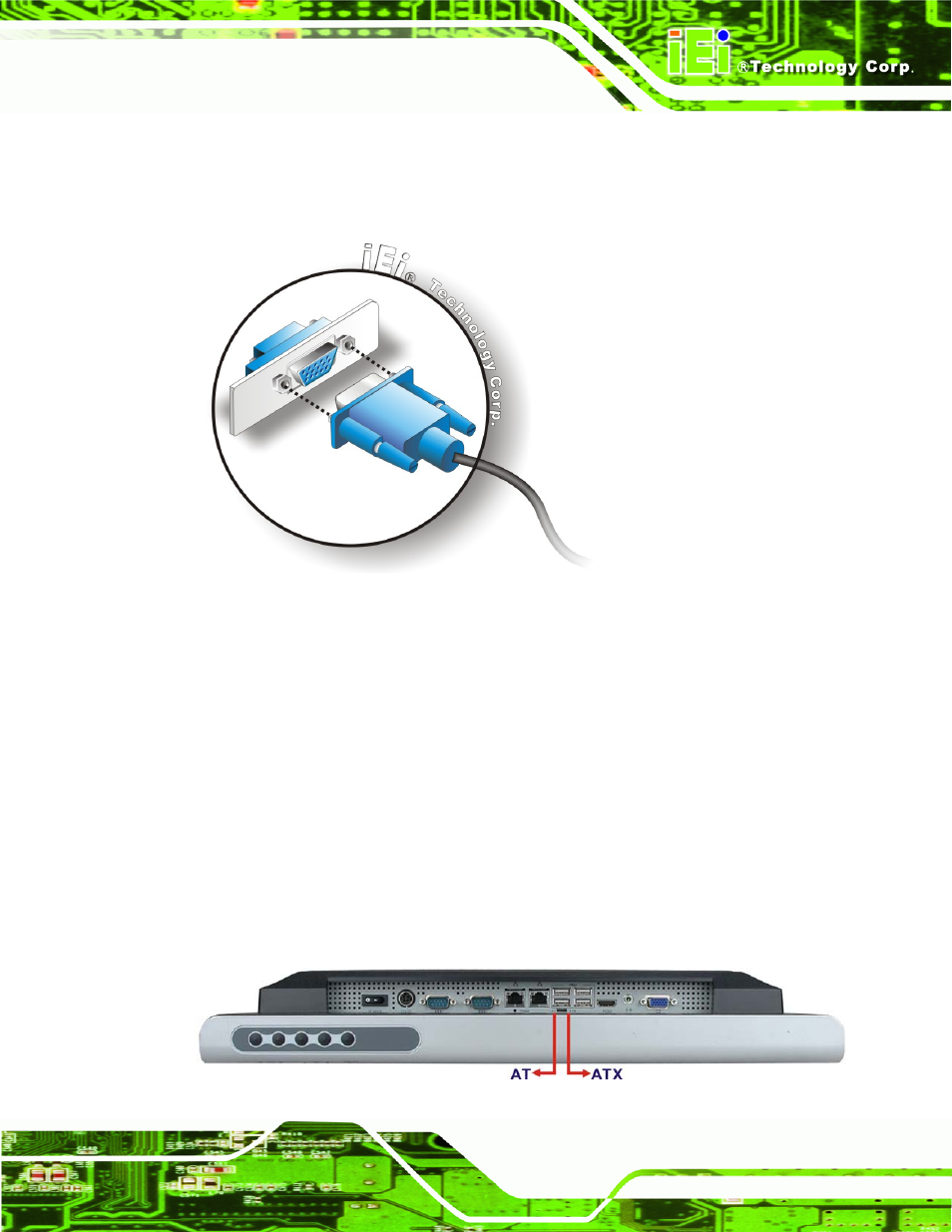
Step 3:
Insert the VGA connector
.
Once the connectors are properly aligned with the
insert the male connector from the VGA screen into the female connector on the
AFL-HM55 Series. See Figure 3-28.
Figure 3-28: VGA Connector
Step 4:
Secure the connector
. Secure the DB-15 VGA connector from the VGA
monitor to the external interface by tightening the two retention screws on either
side of the connector.
Step 0:
3.12 AT/ATX Mode Selection
AT and ATX power modes can both be used on the AFL-HM55 Series. The selection is
made through an AT/ATX switch on bottom panel (Figure 3-29). To select AT mode or
ATX mode, follow the steps below.
Locate the AT/ATX switch on the bottom panel (Figure 3-29).
This manual is related to the following products: